UML Collaboration Diagram
Collaboration Diagram
Collaboration diagrams are like sequence diagrams because of interaction and behavior factors. They are more concerned about object organization rather than sequence diagram that are more focused on a time sequence. They are also known as "Communication Diagram." These are used to represent the flow of messages between the objects.
- The collaboration diagram and sequence diagram shows similar information but in a distinct form.
- It can portray the architecture of an object inside the system.
- It can be used to depict the relationship among various objects within the system.
- The collaboration diagram shows the nature of a specific use case.
- They are used to determine the interfaces and class responsibilities.
- Objects collaborate through passing messages to each other.
Uses of the Collaboration Diagram
- These diagrams design the collaboration among roles and objects that render the functionalities of operations and use cases.
- It models the mechanisms inside an architectural structure of a system.
- The Collaboration diagram models the interactions that represent the passing of messages between the roles and objects inside the collaboration.
- It captures the scenarios in the operations and use cases that contain the collaboration of distinct interactions and objects.
- These diagrams portray the object identification that cooperates in the use cases.
- Every message inside a collaboration diagram contains a sequence number.
- A first message has a sequence number 1. Messages transferred during the call have a similar decimal prefix but have suffixes of 1, 2 accordingly.
Notations
Objects
It is represented through an object symbol depicting the object’s name and their class underlined, isolated by a colon.
You can apply the objects within the collaboration diagram as follows:
- Every object in the collaboration has a name and has a specified class.
- It is not necessary to appear all the classes.
- A class may have one or more objects.
- You can design a collaboration diagram containing objects. You can define their classes later. A class of an object may be undefined.
- The objects can be defined without their name, but you must name them when you wish to segregate the objects belong to the similar classes.
Actors
An instance of an actor takes place in a collaboration diagram, like an invoker of an interaction. When you have various instances in a similar diagram, try to keep them on the brink of the diagram.
- Every actor has a name and its role.
- The discoverer of the use case will only be an actor.
Links
Links connect actors and objects. Every link correlates to the association in a class diagram.
Following is the description of the links:
- A link can be a relation between objects for which messages are transferred. In these diagrams, a link can be displayed just like a sturdy line among two objects.
- An object navigates to another object by its links to such objects.
- A link is an association’s instance, or it is anonymous, it means that the association is unidentified.
- Links are attached to message flow, see messages.
Messages
It is communication among objects that transmits information with an expectation that action will arise. A message can be represented as a specified arrow positioned near the link in the collaboration diagram.
- A message can be conducted from the sender to the receiver.
- The receiver should fathom the message.
- The association should be passable in that direction.
Drawing of the Collaboration Diagram
We can draw the collaboration diagram, when we want to:
- Recognize the behavior whose implementation and realization is specified.
- Recognize the elements (subsystems, objects, and class roles) require to bring the collaboration’s functionality.
- Conclude the situation of interaction: operation, use case, system, and subsystem.
- Create relationships between the elements to render a diagram representing the situation of the interaction.
- Examine an alternative outline that may be needed
- Design the collaboration diagrams on an instance level, if required.
- Optionally design the collaboration diagrams on a specification level. It will help to encapsulate an alternative outline in the sequence diagram instance level.
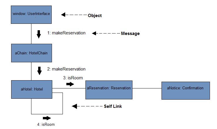
Example:
Advantages of the Collaboration Diagram
- It can also be named as a communication diagram.
- It gives priority to the interaction diagram’s structural facet; that is how the lifelines are attached.
- The structure of a collaboration diagram and sequence diagram is quite similar, but the primary difference is that lifelines do not dwell of tails.
- The messages conveying over sequencing can be shown through numbering to every single message.
- The sequence diagrams are comparatively much durable than the collaboration diagrams.
- The object diagram is a unique or particular case of the collaboration diagram.
- It is more concerned about focusing on elements rather than the flow of messages, as the sequence diagram.
- The sequence diagram can be directly transformed into the collaboration diagram because collaboration diagrams are not much expensive.
- Concerning the sequence diagram, there may be a gamble to squander a piece of information while executing the collaboration diagram.
Disadvantages of the Collaboration Diagram
- A convoluted collaboration diagram can be made by several objects inside the system, as it becomes complex to disclose the objects.
- The collaboration diagram is time exhausting.
- The object will be eradicated when the program abolishes.
- As the state of an object changes instantly, it becomes hard to concentrate on all the single state that has appeared inside the system’s object.
Difference between the Collaboration and Sequence Diagrams
| Sequence Diagram | Collaboration Diagram |
| The sequence diagram is used for enlisting the order of calls within the system, which is applied to produce a particular functionality. | The collaboration diagram is used for enlisting the object’s organization and its interaction. |
| These diagrams are also used to depict the message sequence that is streaming from object to object. | These diagrams are used to portray the system’s structural organization and messages that are transmitted and received. |
| Whenever the time sequence is a primary focus, these diagrams are used. | Whenever the organization of an object is a primary focus, these diagrams are used. |
| The sequence diagram can be better utilized with an analysis activity. | The collaboration diagram can be better utilized when you have to represent the simple interactions of a small number of objects. |