Combinational Logic Circuit
Combinational Logic Circuit
In digital system, Logic circuits generally fall into two categories.
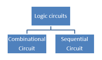
Combinational circuit: - At any instant of time, the output of the logic circuit depends on the inputs of the present combination regardless of its previous inputs. It follows a set of Boolean functions and is used to perform specific data processing. The feedback path and memory elements are absent in this type of circuit.
Examples of combinational circuits are adders, subtractors, comparators, decoders, encoders, and multiplexers.
Sequential circuit: - At any instant of time, the output of the logic circuit depends on the inputs of the present combination as well as on previous (or past) inputs. Along with logic gates, memory elements are also used to store previous input data.
Examples of the sequential circuit are counters, shift-registers, etc.
In this article, we will focus more on combinational circuits.
A combinational circuit is a combination of three things.
- Input variables
- Logic gates
- Output variables
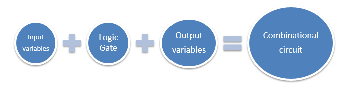
The logic gates receive data from input variables and generate output variables. In this way, the binary data from input is transformed into useful or required data as an output. The information is in the form of binary signals at the ends of both input and output. In general, binary signals have two type of values, i.e., logic-0 or logic-1. At the input end, there can be n-input variables, and at the output end, there can be m-output variables. The source of input variables and output variables are generally known as storage registers.
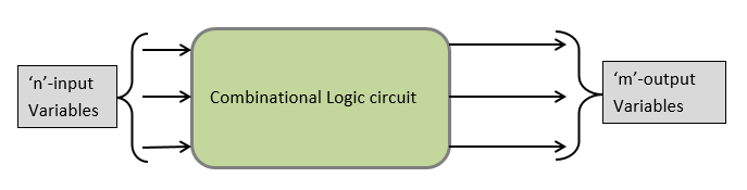
For the ‘n’ number of binary input variables, there is a possibility of a 2n number of combinations. For every combination of inputs, there is only one combination of binary output. Considering each output variable, the total number of Boolean functions can be "m."
The Block diagram of the combinational logic circuit is shown below.
How to design a combinational logic circuit?
- Identify the associated problem.
- Set the value of ‘n’ input variables
- Set the value of "m" output variables
- Assign letter or symbols to all the input and output variables
- Draw the truth table and try to figure out the coordination between input and output
- For every output, write a simplified Boolean function expression
- Finally, draw the logic Diagram
The obtained Boolean output function can be simplified using any method such as algebraic manipulation, the k-map method, or the procedure of tabulation. For each valid combination of input variables, the output can be ‘0’ or ‘1’. Among 2n possible combinations for the n-input variables, it may be possible that some of the combinations will not produce output. And these combinations will become “Don’t care conditions,” which we already discussed in earlier chapters. Being a good designer, we must take care of the following constraints while designing a logic circuit to rectify the stated problems:
- Use minimum no. of gates
- Use minimum no. of inputs variables
- The propagation time of the signal should be minimum
- Use minimum no. of interconnections
Note: - Any combinational logic circuit can be designed using the multiplexers and the universal gates such as NAND or NOR.
Q. Steps to identify any provided circuit is a combinational circuit or sequential circuit?
Answer:- To identify any circuit, whether it is combinational or sequential, the key elements are the presence of feedback path or memory elements or both. In a combinational circuit, there is no feedback path, and it does not contain any memory elements.