Conversion of ER Diagram into Relational Model
After designing the Entity-Relationship diagram, you need to convert it into tables in the relational model. Because the relational model can be easily implemented by the Relational DBMS like Oracle, MySQL, etc.
There are some rules for converting the ER diagram into tables which are as follows:
Rule1: Conversion of an entity set into a table
a) Representation of Strong entity set with simple attributes
Create a relation R for each strong entity set. Simple attributes of an entity set in the ER diagram and relation will be the same. And the key of an ER diagram will become a primary key of the relation.
For example:
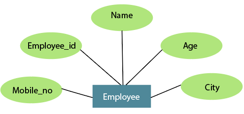
Table: Employee
| employee_id | name | Age | city | mobile no |
b) Representation of Strong entity set with composite attributes
While converting the ER diagram into the Relational model, the composite attributes can be merged as individual columns.
For example:
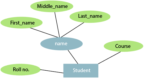
Table: Student
| Roll no | First Name | Middle name | Last name | Course |
c) Representation of Strong entity set with a multivalued attribute
The multivalued attribute is represented by double line ellipse in the ER diagram. While converting the ER diagram into the Relational model, strong entity with multivalued attribute requires two tables in the relational model. One table represents the simple attributes with the primary key, and the other represents all multivalued attributes with the primary key.
For example:
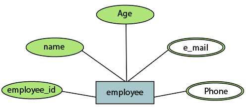
Table: Employee
| Employee_id | Name | Age |
Table: Employee_e-mail
| Employee_id | Phone |
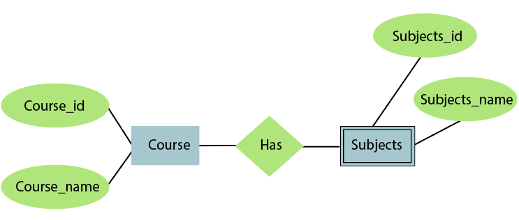
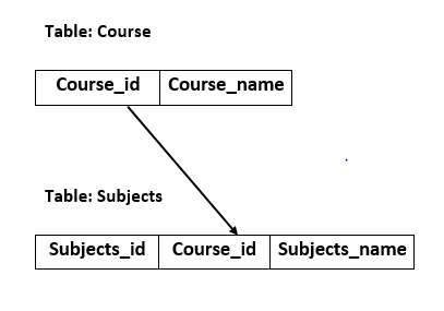
d) Representation of Weak entity set
Create a relation R for each weak entity set. All the attributes of the weak entity set in the ER diagram will become the columns of the relation R. But the key attribute in the ER diagram cannot form the primary key of the relation. You have to add a foreign key, which would be the primary key column of its strong entity.
For example:
In below ER diagram, the Subjects is
the weak entity set. Hence, create a relation for it. The field Subjects_id and
Subjects_name form the column of this relation. Although Subjects_id is represented as a key attribute in the ER diagram, it
cannot be considered as a primary key in the relation model. To add the primary
key to the field in the relation, find the foreign key first. The Course is the strong entity related to Subjects. Hence, the Course_id, which is a primary key of Course, is added to Subjects relation as a foreign key. Now, create a composite key by using Course_id and Subjects_id.
Rule 2: Conversion of Relationship into relation
Create a relation for each relationship and add the primary keys of all participating entities as an attribute of relation with their respective data types. If a relationship in an ER diagram has any attribute, add each attribute as a column of relation. Declare all foreign key constraints and a primary key composing all the primary keys of participating entities.
For example:
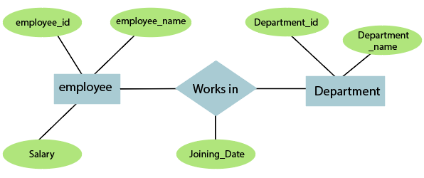
Table: Works_in
| Joining_Date | employee_id | Department_id |