Data Encapsulation and De-Encapsulation
Data Encapsulation
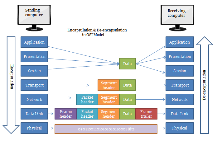
It is the process of adding headers and trailers to data. When a host transmits data to another device over a network, the data is encapsulated, with protocol information at each layer of the OSI reference model. Each layer uses Protocol Data Units (PDUs) to communicate and exchange information from source to the destination.
Encapsulation: Data-> Segment-> Packet-> Frame-> Bits
(From application layer to physical layer)
Protocol Data Unit (PDU)
- It is a combination of data and control information attached to each layer of the OSI reference model.
- Control information in the transport layer may include:
- Destination Service Access Point (DSAP)
- Sequence number
- Error-detection code
- Each Protocol Data Unit has a name depending on the information stored in each header.
The Protocol Data Unit of each layer is defined as follows:
Transport Layer: Segment is the PDU.
Network Layer: Packet is the PDU.
Data link layer: Frame is the PDU.
Physical layer: Bit is the PDU.
Encapsulation and De-Encapsulation Process
The Encapsulation and de-encapsulation is the process of how to attach control information at each layer of the OSI reference model is as follow:
TCP Header Encapsulation
The upper layers (Application, Presentation, and Session) user data send on a network for transmission. The data is then broken up, and a Transport layer header is created that is called a segment.
A segment stores information such as the source and destination ports or sequence and acknowledgment numbers. Once segments are created, they are handed down to the network layer for further processing.
IP Header Encapsulation
Network layer creates a header for a received segment from the Transport layer. This header contains source and destination IP addresses. Once the header is attached, the segment is called a packet. Packets are handed down to the next layer, i.e., Data link layer.
MAC Header Encapsulation
Data link layer receives packets from the Network layer. It creates both header and trailer for each received packet. It contains information such as source Mac address and destination Mac address. Once header and trailer attached with the packet, it is called a frame. Frames are handed down to the physical layer.
Physical Layer Encapsulation
It receives frames from the data link layer and converts it into a digital signal. If the host connected with a wire, the physical layer will convert frames into voltage. And if the host connected with a wireless network, the physical layer will convert frames into radio signals.
Data Encapsulation Flow
The Data Encapsulation flow works like this:
- The data is sent from the Upper layer (Application layer) to the Transport layer.
- The Transport layer encapsulates the data and adds its own header with its own information, such as source and destination port number, Sequence, and acknowledgment number will be used and passes the data to the Network layer.
- The Network layer encapsulates the received data and adds its own header, usually with information about the source and destination IP addresses. The Network layer than passes the data to the Data link layer.
- The Data link layer is the only layer that adds both a header and a trailer. The data is then sent through a physical layer.
- The Physical layer is used to convert the data to bits.
De-Encapsulation
It is a reverse of Encapsulation. In this process, header and trailer attached in Encapsulation are removed.
De-Encapsulation: Bits -> Frame-> Packet -> Segment-> Data
(From Physical layer to Application layer)
The Data De-Encapsulation flow works like this:
- First, the receiver's computer will synchronize with the digital signal, then it will receive the whole frame to pass it to the above data link layer.
- In the data link layer, an error detection method, i.e., Cyclic Redundancy Check, will occur in the frame to check errors in the data. It will remove the headers which are added previously and pass rest data to the above network layer.
- The network layer will check and match the IP address. If matches, then it will remove the IP header from the packet and rest is sent to above layer, i.e., Transport layer.
- The transport layer is processed and rebuilt the data stream and acknowledgments to the receiver that it has received the data.
- Then it hands over the data to upper layers.
The Cisco Three-Layer Hierarchical Model
- This model is designed to make networks more predictable.
- Hierarchy helps us to summarize a complex collection of details into an understandable model.
- It also helps us to design, implement, and maintain a scalable, cost-effective, reliable hierarchical network.
Advantages of Three-Layer Hierarchical Model
- Easy to Understand
- Flexibility
- Cost Saving
- Easily Modified
- Allows Network Growth
The following are three layers and their functions:
- Core layer – Backbone
- Distribution layer – Routing
- Access layer – Switching
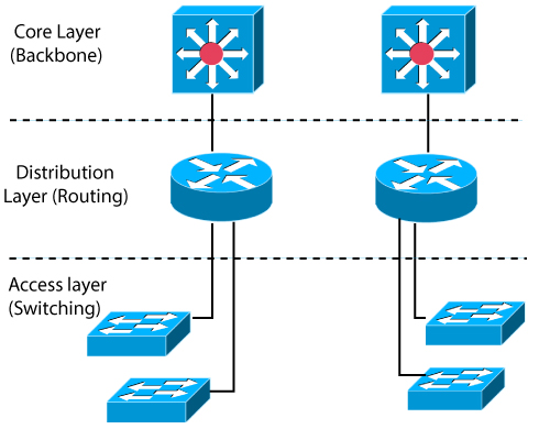
Core Layer
- It is the backbone of the network.
- It is responsible for transporting a large amount of traffic reliably and quickly.
- Fault tolerance at this layer is a big issue because if there is a failure in the core, every single user can be affected.
Network equipment used in the core layer are:
High-speed WAN routers and switches, ATM Networks, Cisco 7000, 7200, 7500 and 12000 series router and switches for WAN and Cisco 4000, 5000 and 6000 series router and switches for LAN.
Distribution Layer
- This layer is referred to as the workgroup
- It is the communication point between the access layer and the core.
- The distribution layer determines the best way that network service requests are handled for example, how a file request is forwarded to a server.
- After determines the best path, the distribution layer forwards the request to the core layer if necessary.
There are the following functions to be done at the distribution layer:
- Routing
- Implementing tools (access lists), packet filtering, and queuing.
- Implementing security and network policies, such as address translation and firewalls.
- Defining broadcast and multicast domains.
Access Layer
- This layer is referred to as the desktop
- It provides workgroup’s and users’ direct access to the network.
- Access layer devices include hubs, Switches, computers, printers, and multi-station access units.
- There are following functions to be done at the access layer:
- Creation of the separate collision domains.
- Workgroup connectivity into the distribution layer
- Technologies such as Fast Ethernet switching seen in this layer.