UML Sequence Diagram
Sequence Diagram
The sequence diagram is not only featured for the design model but also characterized for depicting the business processes because of its certain features. As its name defines, interaction and messages can properly be sequenced by the use of a sequence diagram. Actors and objects are essential in this diagram. They will get activated when needed or if any other object wants to interact with them.
- A sequence diagram is used to illustrate the message flow inside the system.
- It is also known as an event diagram.
- It absorbs the branching as well as iterations.
- A dotted vertical line can express a message, and lifelines can be illustrated by a vertical bar in UML that spreads crosswise the base of a page.
Aim of the Sequence Diagram
- It aims to model an interaction between active objects inside a system.
- It designs some interaction instances or generic interactions.
- It also designs interaction between objects within a collaboration recognizing the use case.
Notations `
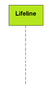
Lifeline
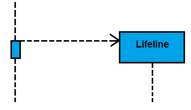
A lifeline can represent a participant in this sequence diagram. In the sequence diagram, it can be located at the top.
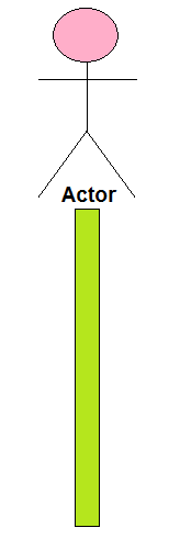
Actor
An actor serves the performance, which associates external behavior or subjects and human users. It may or may not produce a physical entity, but it can express the performance of the entity. Sequence diagrams may also serve various performances performed by an actor.
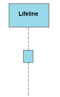
Activation
A fragile rectangle can express it on a lifeline. The activation notation defines a time period through which a process is behaved by a component. So both the edges (top and bottom) can be attached with the initiation time and completion time, respectively.
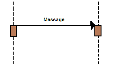
Message
There are some types of messages discussed below:
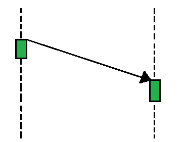
- Call Message: Call message describes the communication among the interaction’s lifeline, which illustrates that an objective lifeline has conjured an operation.
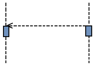
- Return Message: Return message describes a specific communication among the interaction’s lifeline that illustrates the information flow from the assignee of the caller message.
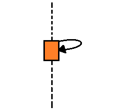
- Self Message: Self message defines a communication among the interaction’s lifeline that expresses a message that has been conjured of a similar lifeline.
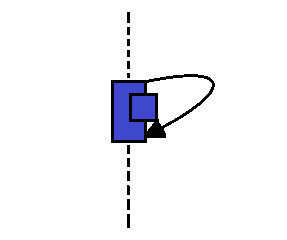
- Recursive Message: Any self message transmitted for recursive goals is known as a recursive message.
- Create Message: Particularly, it defines a communication among the interaction’s lifeline depicting that an objective lifeline has been instantiated.
- Duration Message: Duration message defines a conversation among the interaction’s lifeline that depicts a time period of a message when designing a system.
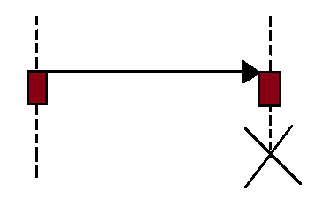
- Destroy Message: Destroy message defines a conversation among the interaction’s lifeline that portrays an appeal for destroying the target’s lifecycle.
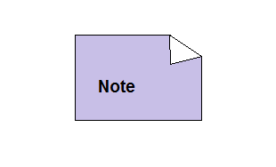
Note
It is an efficiency of connecting various remarks to an element. It can carry some useful data for modelers.
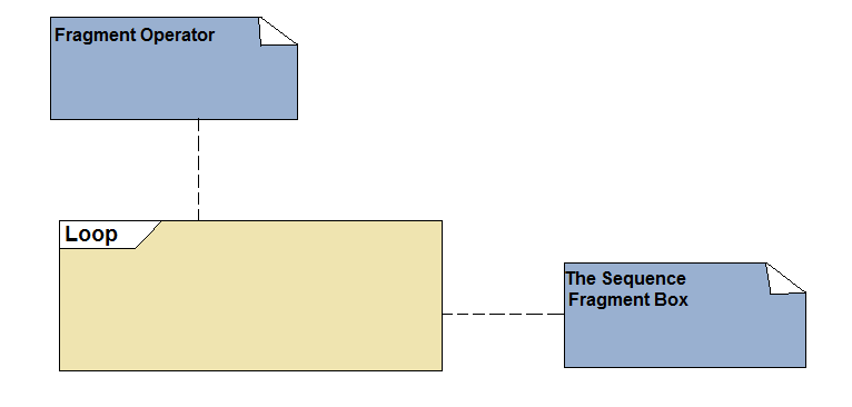
Sequence Fragments
- UML 2.0 defines these sequence fragments. It can be used for creating and maintaining an authentic sequence diagram.
- It is illustrated by a box which is called the combined fragment.
- A fragment operator expresses a type of the fragment.
- Fragment type: assert, alt, break, loop, opt, neg, ref, etc.
| Operator | Fragment type |
| alt | Alternative Multiple Fragments: This is the fragment for which the satisfied condition will be implemented. |
| opt | Optional: If the supplied condition is met, the fragments will be implemented. It is the same as alt with only a trace. |
| par | Parallel: Parallel implements fragments. |
| loop | Loop: Fragments can run several times, and the basis of interaction is displayed through the guard. |
| region | Critical Region: Only one tread can implement a fragment only once. |
| neg | Negative: The fragment shows an ineffective communication. |
| ref | Reference: An interaction is depicted in other diagrams. A frame is designed to cover up the lifelines contained in the communication. The return value and parameter can be analyzed. |
| sd | Sequence Diagram: It is applied to surround the entire sequence diagram. |
Types of Sequence Fragments
Use of Sequence Diagram
- It is used to visualize and model the reasoning behind a procedure, operation, or a sophisticated function.
- These diagrams are used to display the specifics of the use case diagrams in UML.
- The sequence diagram also used to grasp the specified functionalities of prevailing and an eventual system.
- It can visualize the movement of tasks and messages between components and objects in the system.
Peek of the Sequence Diagram
Sequence diagrams are established according to time (vertically) and object (horizontally). They are capable of expressing how the elements collaborate over time.
Time Dimension
- The time progressing (proceedings) can be represented by the vertical axis downward the page.
Object Dimension
- The elements can be shown by the horizontal axis that is committed in an interaction.
- However, various elements can take any order to display them on the horizontal axis. When the objects grasp part in the sequence message, they are committed in operation and enlisted from the left side to the right side accordingly.
When to Use Sequence Diagram
We can use the sequence diagram, when we want to:
- Design high-level cooperation between various active objects within a system.
- Design the cooperation between instances of objects inside the collaboration that comprehends the use case.
- Design the cooperation between objects inside the collaboration that comprehends an operation.
- Either design:
- Generic interactions: Displaying all the paths from the interaction
- Specific interaction’s instances: Displaying only one way from the interaction
Advantages
- It is convenient to generate.
- It has convenient maintenance.
- It portrays the flow of messages between various objects.
- It can be used to execute forward engineering and reverse engineering as well.
- It can conveniently update according to the changes in a system.
- It scrutinizes various real-time operations.
Disadvantages
- Every sequence requires several
notations for their representation, so it can make these diagrams more
complicated.
The sequence type can be elected through the message type. - The sequence diagram may get convoluted if there are so many lifelines present in the system.
- When the sequence of the message flow modifies, then it may be possible to generate an incorrect outcome.
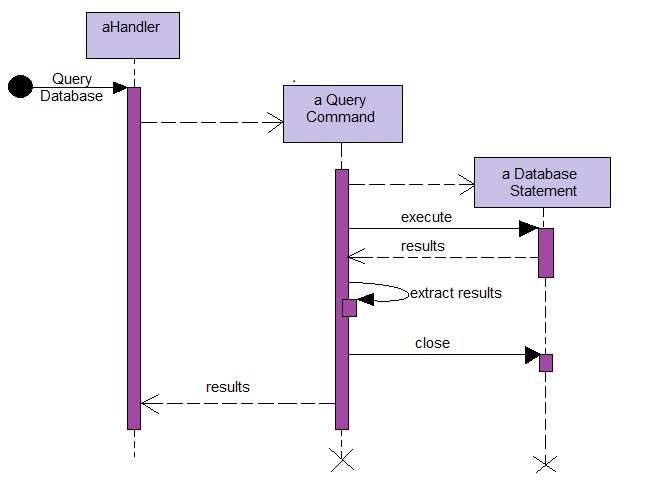
Example of Sequence Diagram
The following example defines that in an interaction modeling can use a recursive message: