UML Deployment Diagram
Deployment Diagram
Deployment diagrams have some similarities like component diagrams. The component diagrams are used for characterizing the components. In contrast, deployments diagrams are used to expand these components in the context of the hardware. They have two most important factors, which are as follows:
- Nodes
- The connection between these nodes
These diagrams are mainly used for physical components that are also called as hardware components. Component and deployments diagrams are the only diagrams among all other diagrams that are used for both software and hardware components, while other diagrams are only used for software components. System engineers mostly use these diagrams. It can control various types of parameters such as performance, scalability, portability, and maintainability.
When to apply Deployment Diagram
We can apply Deployment diagram during some questions in mind, which are listed below:
- What an existing system will the freshly combined system require to integrate or interact with?
- How potent does the system require to be?
- Who and what will connect to the system, and how will they do it?
- What the system use, including communication mechanisms, operating system, and protocols?
- What software and hardware will customers interact with directly (browsers, network computers, PCs, etc.)?
- How will audit the system at least once exploited?
- How much protected any system is required to be (physically protect hardware, needs firewall, etc.)?
Aims of Deployment Diagrams
- The architecture of the system can be planned using this diagram.
- These diagrams apprehend the links among various hardware items and the hardware that will be used to execute the system.
- Component diagrams display the structure of a run-time system.
- These diagrams will help to document the formation of nodes or software components.
- These diagrams also create a communication path between the physical hardware components.
Peek of Deployment Diagram
These diagrams are essential for managing the system by reverse engineering and forward engineering and also for specifying, visualizing, client/server, distributed systems, and documenting embedded. In other words, it is a unique type of class diagram, which concentrates on the node of the system. A deployment diagram is a set of arcs and vertices, graphically.
Component diagram contains:
Nodes
- Nodes can be placed within other nodes.
- Node HW can be proclaimed with <<stereotype>>
- A 3D box shows either a hardware or software node
- Connections among nodes can be explained by a line, with an optional <<stereotype>>
Other Notations
- Dependency relationships
- Association relationships
- Also, contain constraints and nodes
How to Model Component Diagram
The topology of the system can be visualized using a deployment diagram. In this diagram, nodes can implement the artifacts. The artifact instances expand on the nodes instances.
It comprises of the following factors in an administrative process:
- Scalability
- High Performance
- Easily understandable
- Portability
- Maintainability
It is necessary to determine every relationship and node between artifacts and nodes. It will easy to develop this diagram when artifacts, their relationships, and the nodes that are already known.
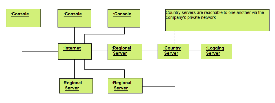
Example – A Fully Distributed System
- Determine the processors and devices of the system, just like a simple client/server system.
- Pay extra consideration to the logical organization of nodes, for which you can specify through packages.
- You can model these processors and devices with the use of a component diagram. Apply tools that identify the topography of the system through your network of the system.
- It is prevalent to emerge the network as a node when you are modeling a distributed system like nodes, LAN, WAN, internet.
The following example shows a complete distributed system: