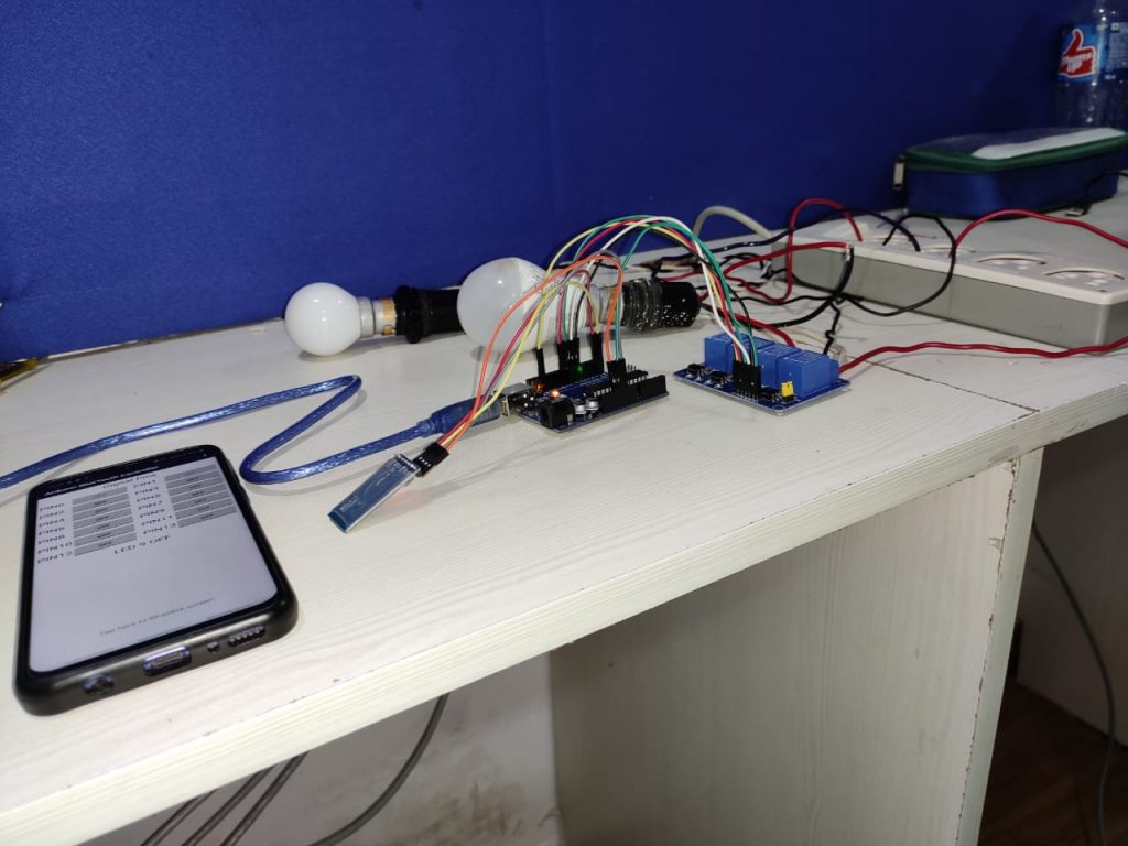
Arduino UNO Home Automation
Build a Bluetooth controlled Home Automation Setup Using Arduino UNO board and Relay module
- Do you want to automate your home?
- Have you ever wanted to control your home appliances by swipe the screen of your phone?
- Do you want to learn how to build an automation device for yourself?
In this project, we will see how to control a light bulb, fan, or other electrical devices in your home with an Arduino board. At the end of the project, you can control the connected load from your Smartphone.
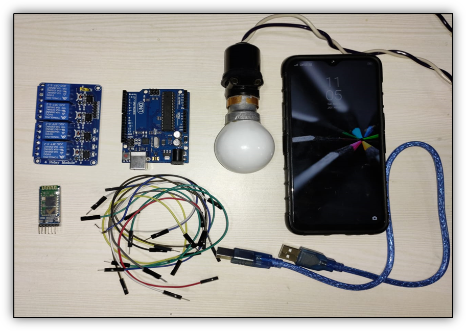
Requirements of hardware in this Project:
- Arduino UNO board
- Relay module (5V)
- Bluetooth Module HC-05
- Jumper wires male to female
- Light bulb
- A USB cable for connecter Arduino UNO board
- Android Phone
Requirements of software in this Project:
- Arduino IDE software (To program the Arduino board, we need to download the Arduino software)
- Android (Arduino Bluetooth controller App)
The Working principle of this Project:
There are four main components used:
- Android Smartphone
- Bluetooth module
- Arduino UNO board
- Relay module
The Android application sends the data in series to the connected Bluetooth module HC-05 by clicking “ON” button. The Bluetooth module receives the application data and sends it through the TX pin of the Bluetooth module to the Arduino RX pin. The Arduino board reads the input data, processes it according to the program loaded inside and generates the output to the Relay Module.
Write a program in the Arduino IDE.
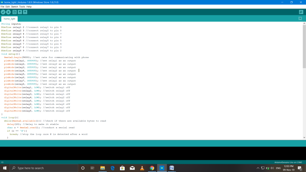
Full code show in below:
 String inputs;
 #define relay1 2 //connect relay1 to pin 9
 #define relay2 3 //connect relay2 to pin 8
 #define relay3 4 //connect relay3 to pin 7
 #define relay4 5 //connect relay4 to pin 6
 #define relay5 6 //connect relay5 to pin 5
 #define relay6 7 //connect relay6 to pin 4
 #define relay7 8 //connect relay7 to pin 3
 #define relay8 9 //connect relay8 to pin 2
 void setup(){
Serial.begin(9600); //set rate for communicating with phone
pinMode(relay1, OUTPUT); //set relay1 as an output
pinMode(relay2, OUTPUT); //set relay2 as an output
pinMode(relay3, OUTPUT); //set relay1 as an output
pinMode(relay4, OUTPUT); //set relay2 as an output
pinMode(relay5, OUTPUT); //set relay1 as an output
pinMode(relay6, OUTPUT); //set relay2 as an output
pinMode(relay7, OUTPUT); //set relay1 as an output
pinMode(relay8, OUTPUT); //set relay2 as an output
digitalWrite(relay1, LOW); //switch relay1 off
digitalWrite(relay2, LOW); //switch relay2 off
digitalWrite(relay3, LOW); //switch relay1 off
digitalWrite(relay4, LOW); //switch relay2 off
digitalWrite(relay5, LOW); //switch relay1 off
digitalWrite(relay6, LOW); //switch relay2 off
digitalWrite(relay7, LOW); //switch relay1 off
digitalWrite(relay8, LOW); //switch relay2 off
}
void loop(){
while(Serial.available()){ //check if there are available bytes to read
delay(10); //delay to make it stable
char c = Serial.read(); //conduct a serial read
if (c == '#'){
break; //stop the loop once # is detected after a word
}
inputs += c; //means inputs = inputs + c
}
if (inputs.length() >0){
Serial.println(inputs);
if(inputs == "A"){
digitalWrite(relay1, LOW);
}
else if(inputs == "a"){
digitalWrite(relay1, HIGH);
}
else if(inputs == "B"){
digitalWrite(relay2, LOW);
}
else if(inputs == "b"){
digitalWrite(relay2, HIGH);
}
else if(inputs == "C"){
digitalWrite(relay3, LOW);
}
else if(inputs == "c"){
digitalWrite(relay3, HIGH);
}
else if(inputs == "D"){
digitalWrite(relay4, LOW);
}
else if(inputs == "d"){
digitalWrite(relay4, HIGH);
}
else if(inputs == "E"){
digitalWrite(relay5, LOW);
}
else if(inputs == "e"){
digitalWrite(relay5, HIGH);
}
else if(inputs == "F"){
digitalWrite(relay6, LOW);
}
else if(inputs == "f"){
digitalWrite(relay6, HIGH);
}
else if(inputs == "G"){
digitalWrite(relay7, LOW);
}
else if(inputs == "g"){
digitalWrite(relay7, HIGH);
}
else if(inputs == "H"){
digitalWrite(relay8, LOW);
}
else if(inputs == "h"){
digitalWrite(relay8, HIGH);
}
inputs="";
}
}
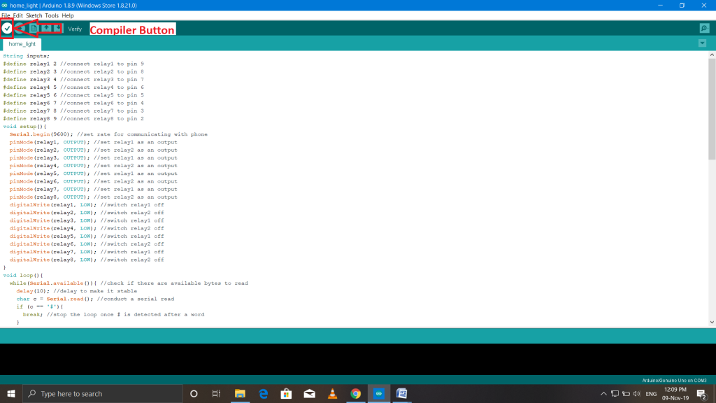
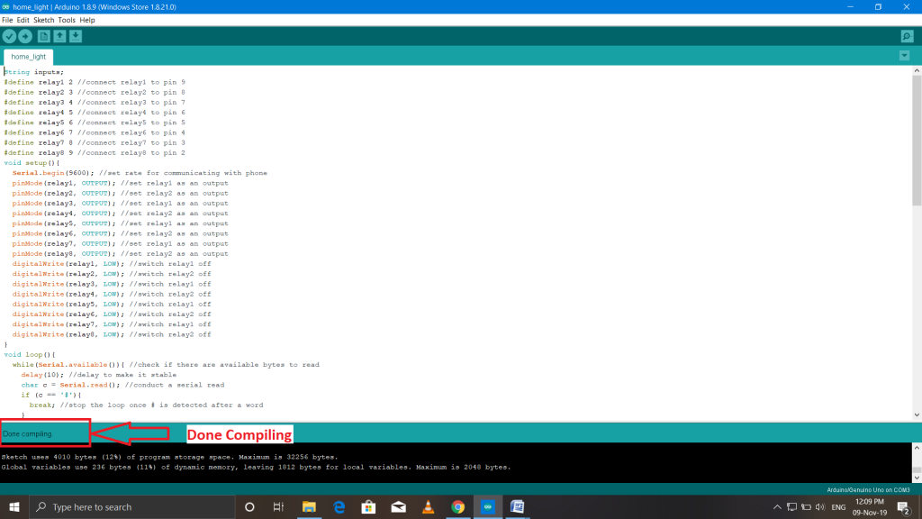
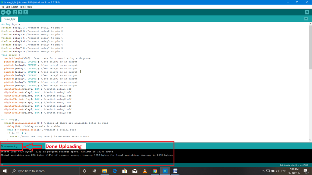
Save your program and compile, as shown in the following figure
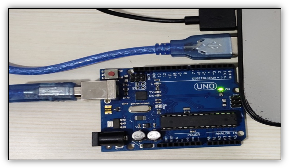
Connect your Arduino UNO board to your laptop or desktop computer through the Arduino UNO USB cable. Remove all other connections with the Arduino UNO board, such as the Bluetooth module and Relay module, and then “Upload the program to the Arduino UNO board”. The following figure shows the Arduino UNO board and the cables connected with that.
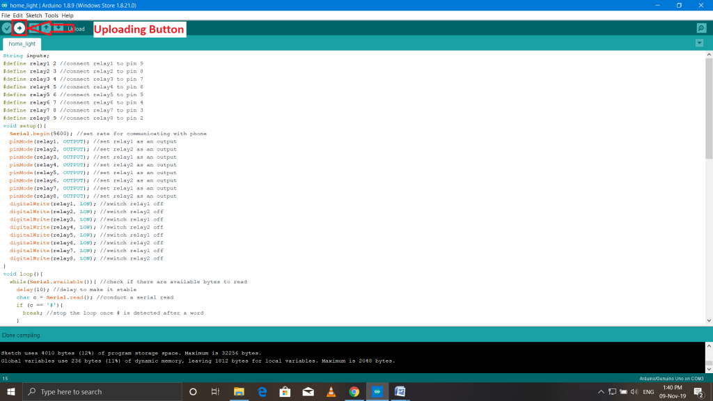
Before uploading the code to the Arduino UNO board, make sure your Arduino serial port is selected. Otherwise, an error message "Serial port not selected" is shows on the screen.
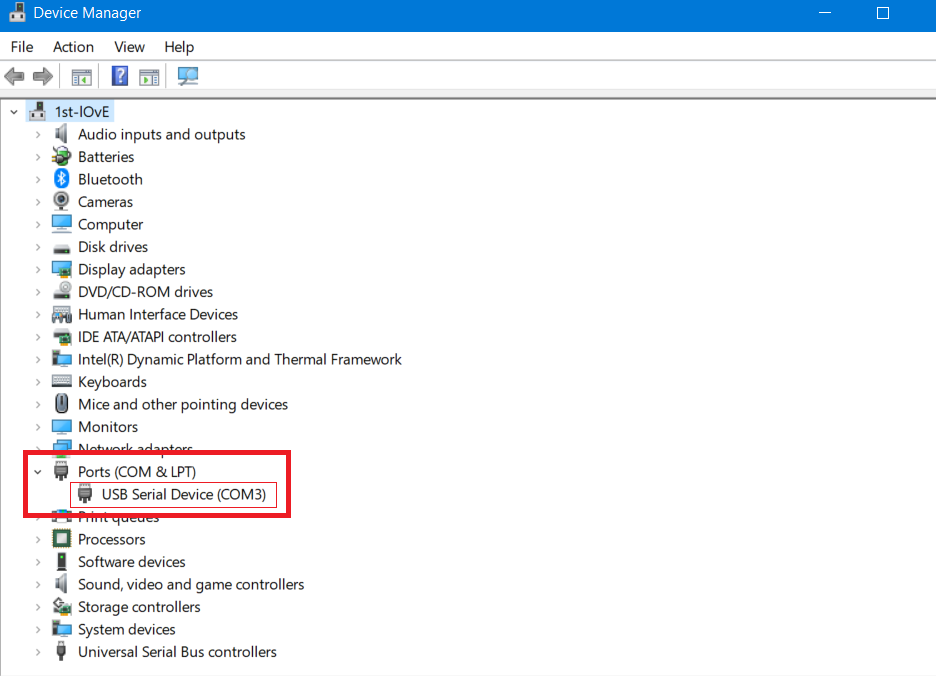
To select your serial port in your laptop or desktop:
Open Device Manager -> Ports (COM & LPT) ->Arduino Uno, and then upload your program.
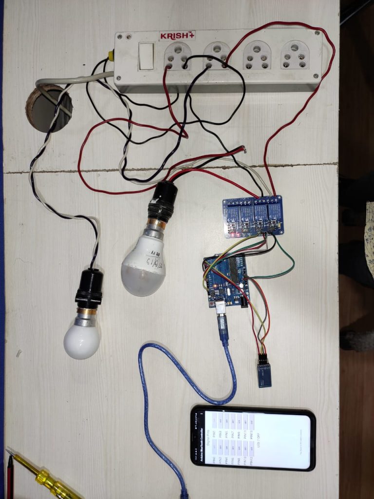
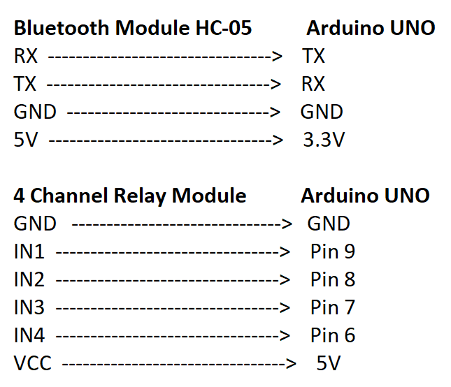
After uploading the program in the Arduino UNO board. Connect all modules with the Arduino UNO board, such as the Bluetooth module and Relay module. The following image shows the "Digital circuit diagram."
Connection between Relay Module, Bulb, and input power:
- Connect common-point (com) of Relay Module with home light.
- Connect normally-close (nc) of Relay Module with power.
- Connect remaining one home light wire with the power source.
Circuit Diagram Relay module with Light Bulb
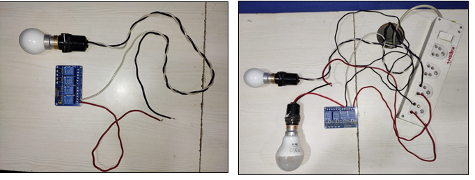
Connect all the modules with the Arduino UNO board, and light bulb with Relay.
Now, Connect Bluetooth modules HC-05 with the Android Smartphone. Consider the screenshots below:
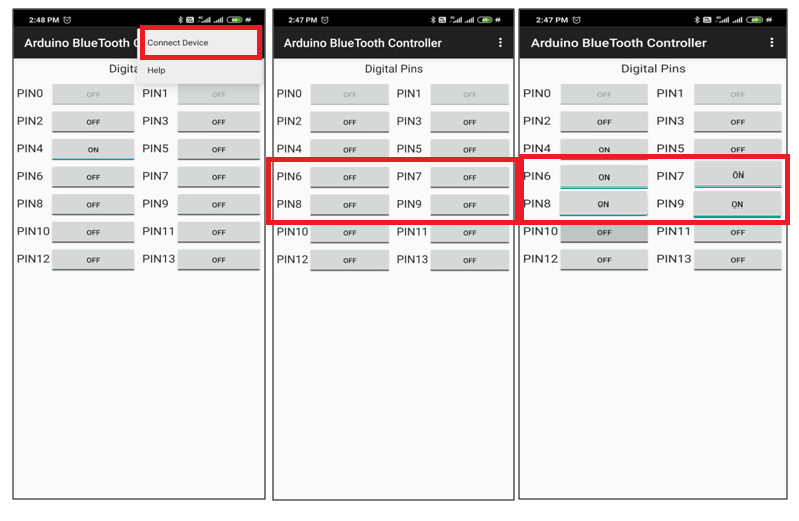
Note: Channel Relay module works only with PIN 6, PIN 7, PIN 8, and PIN 9.
When we click on the “ON” button of PIN 6, PIN 7, PIN 8, and PIN, the android application sends 1 to the Bluetooth module. The data is transmitted from the Bluetooth module to the Arduino board. As soon as the Arduino board gives permission to the Relay module for the power supply, the home appliance turns ON.
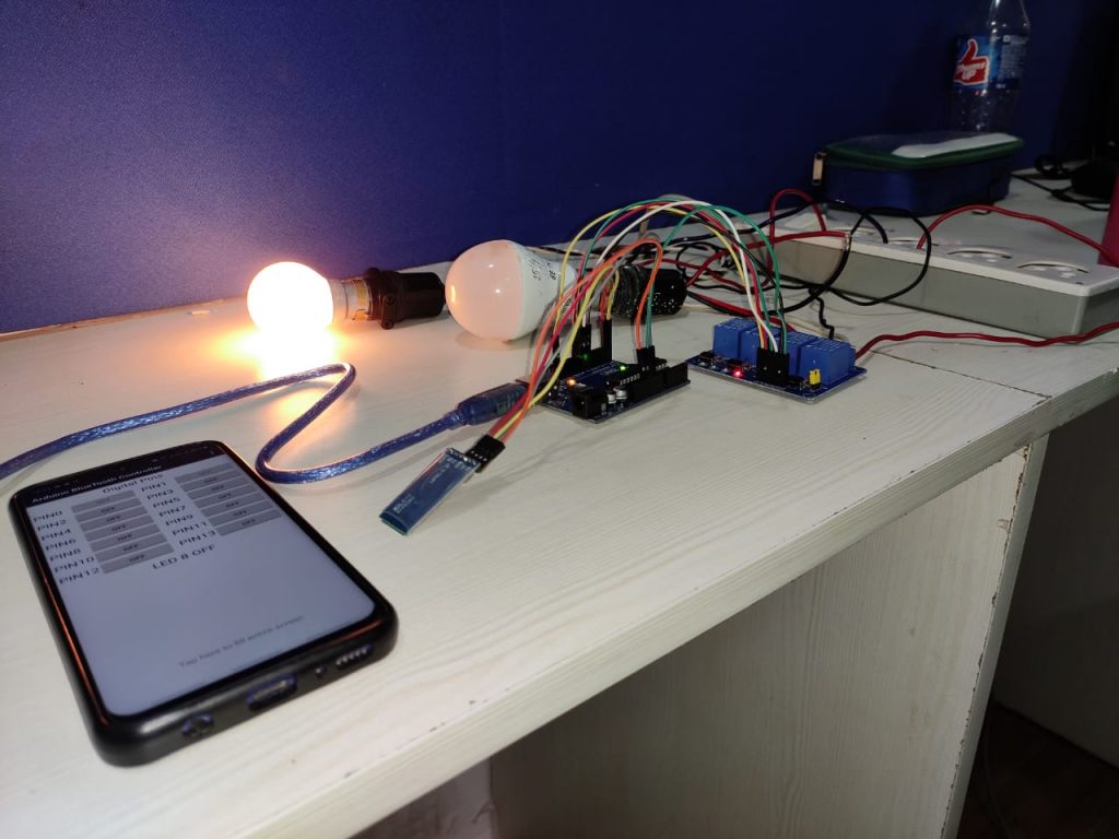
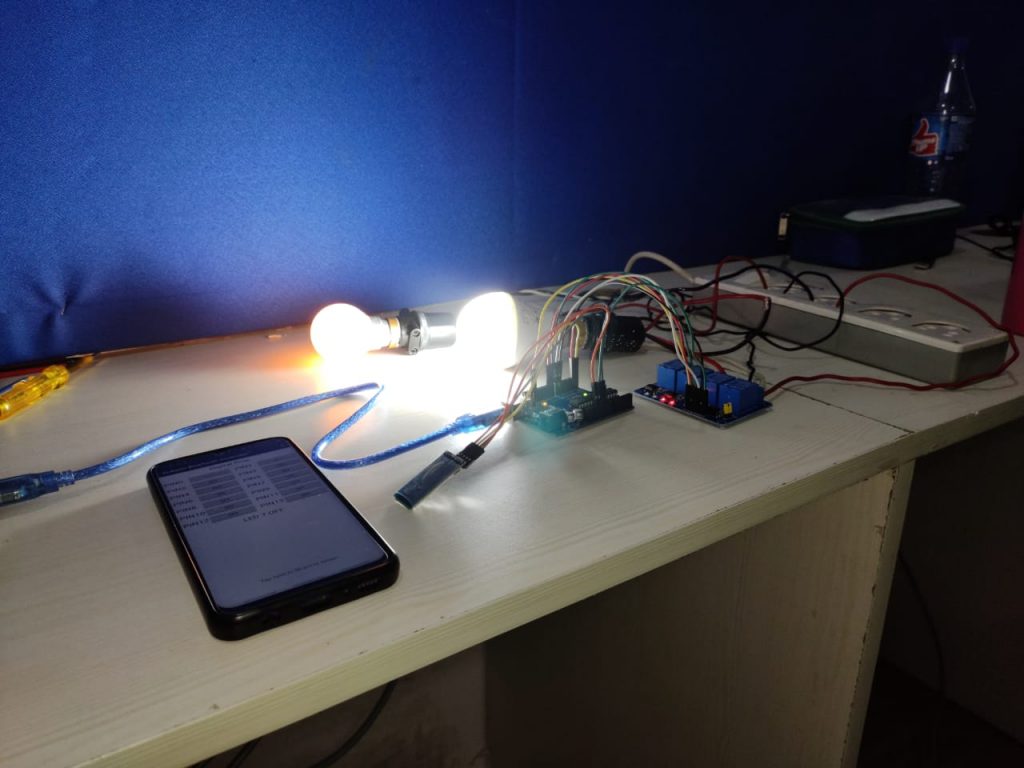
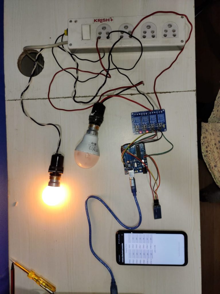
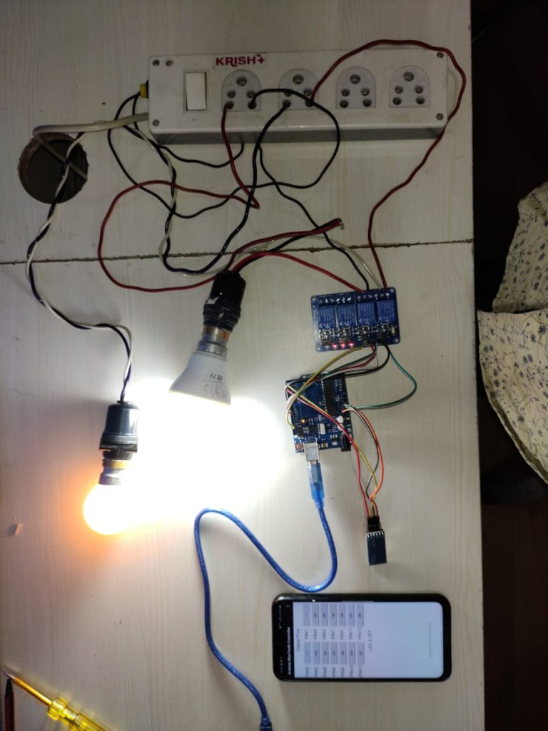
When we click on the OFF button of the PIN 6, PIN 7, PIN 8, and PIN 9, the Android application sends 0 to the Bluetooth module. The data is transmitted from the Bluetooth module to the Arduino device, and the home appliances turns OFF.