
Basic Blocks and Flow Graphs in Compiler Design

Basic Blocks and Flow Graphs

In this section, we are going to learn how to work with basic block and flow graphs in compiler design.

Basic Block

The basic block is a set of statements. The basic blocks do not have any in and out branches except entry and exit. It means the flow of control enters at the beginning and will leave at the end without any halt. The set of instructions of basic block executes in sequence.

Here, the first task is to partition a set of three-address code into the basic block. The new basic block always starts from the first instruction and keep adding instructions until a jump or a label is met. If no jumps or labels are found, the control will flow in sequence from one instruction to another.

The algorithm for the construction of basic blocks is given below:

Algorithm: Partitioning three-address code into basic blocks.

Input: The input for the basic blocks will be a sequence of three-address code.

Output: The output is a list of basic blocks with each three address statements in exactly one block.

METHOD: First, we will identify the leaders in the intermediate code. There are some rules for finding leaders, which are given below:

  1. The first instruction in the intermediate code will always be a leader.
  2. The instructions that target a conditional or unconditional jump statement are termed as a leader.
  3. Any instructions that are just after a conditional or unconditional jump statement will be a leader.

Each leader’s basic block will have all the instructions from the leader itself until the instruction, which is just before the starting of the next leader.

Example:

Consider the following source code for a 10 x 10 matrix to an identity matrix.

for i from 1 to 10 do
         for j from 1 to 10 do
            a [ i, j ] = 0.0;
 for i from 1 to 10 do
            a [ i,i ] = 1.0; 

The three address code for the above source program is given below:

1) i = 1
 2) j = 1
 3) t1 = 10 * i
 4) t2 = t1 + j
 5) t3 = 8 * t2
 6) t4 = t3 - 88
 7) a[t4] = 0.0
 8) j = j + 1
 9) if j <= 10 goto (3)
 10) i = i + 1
 11) if i <= 10 goto (2)
 12) i = 1
 13) t5 = i - 1
 14) t6 = 88 * t5
 15) a[t6] = 1.0
 16) i = i + 1
 17) if i <= 10 goto (13) 
  • According to the given algorithm, instruction 1 is a leader.
  • Instruction 2 is also a leader because this instruction is the target for instruction 11.
  • Instruction 3 is also a leader because this instruction is the target for instruction 9.
  • Instruction 10 is also a leader because it immediately follows the conditional goto statement.
  • Similar to step 4, instruction 12 is also a leader.
  • Instruction 13 is also a leader because this instruction is the target for instruction 17.

So there are six basic blocks for the above code, which are given below:

B1 for statement 1

B2 for statement 2

B3 for statement 3-9

B4 for statement 10-11

B5 for statement 12

B6 for statement 13-17.

Flow Graph

It is a directed graph. After partitioning an intermediate code into basic blocks, the flow of control among basic blocks is represented by a flow graph. An edge can flow from one block X to another block Y in such a case when the Y block’s first instruction immediately follows the X block’s last instruction. The following ways will describe the edge:

  • There is a conditional or unconditional jump from the end of X to the starting of Y.
  • Y immediately follows X in the original order of the three-address code, and X does not end in an unconditional jump.
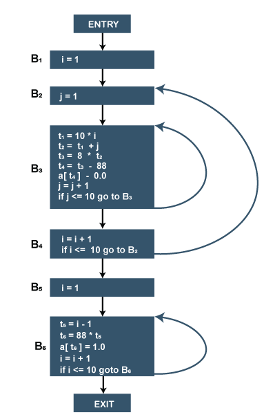
Basic Blocks and Flow Graphs in Compiler Design

Flow graph for the 10 x 10 matrix to an identity matrix.

  • Block B1 is the entry point for the flow graph because B1 contains starting instruction.
  • B2 is the only successor of B1 because B1 doesn't end with unconditional jumps, and the B2 block's leader immediately follows the B1 block's leader.
  • B3 block has two successors. One is a block B3 itself because the first instruction of the B3 block is the target for the conditional jump in the last instruction of block B3. Another successor is block B4 due to conditional jump at the end of B3 block.
  • B6 block is the exit point of the flow graph.

Related Topics

LALR 1 Parsing | Compiler Design

LALR (1) Parsing The LALR parsing refers to the "lookahead LR" that has many lesser steps than typical parsers based on LR(1) items. For constructing the LALR(1) parsing table, the canonical...

6 minutes read.

Run-Time Environments

Run-Time Environments Storage Organization Every target program has its own logical address, and an executable program runs in it. The logical address space has the location for each program value. The...

2 minutes read.

Stack Allocation of Space

Stack Allocation of Space Almost all compilers for languages that use procedure, functions, or methods manage their run-time memory as a stack. Whenever a procedure is called, the local variable's space...

2 minutes read.

Code Generation

Code Generation The last phase of the compiler is code generation. It is the compiler's back-end that makes multiple passes over the IR before generating the target program. The code generator's...

4 minutes read.

Optimization of Basic Blocks in Compiler Design

Optimization of Basic Blocks We can apply the optimization process on a basic block. While optimization, there is no need to change the set of expressions computed by the block. The basic...

3 minutes read.

Storage Allocation

Storage Allocation The storage allocation represents memory management. The allocation of memory can be done in the following ways: Static AllocationStack AllocationHeap Management Static Allocation: It is a procedure used for the allocation of...

1 minute read.

Errors in Compiler Design

Introduction Errors in compiler design refer to mistakes or issues that arise during the process of execution of the program. A compiler is a program that translates source code written in...

4 minutes read.

Evolution of Programming Languages in Compiler Design

The Evolution of Programming Languages The first computer came in the 1940s and was programmed in a binary language that told the computer what operations are to be performed and in...

4 minutes read.

Three-Address Code

Three-Address Code If there is at most one operator on the right side of the instruction, then the instruction will be the three-address code so that no arithmetic expressions are permitted....

2 minutes read.

CLR Parsing Compiler Design

CLR Parsing CLR parsing refers to the canonical lookahead. We will use the canonical collection of LR(1) items for the construction of the CLR(1) parsing table. Generally, CLR(1) parsing has more...

6 minutes read.

Syntax Analysis Compiler Design

Syntax Analysis This article will describe the parsing method used in the compiler. The grammatical rule of programming language can be constructed with the help of context-free grammars or BNF (Backus–Naur...

3 minutes read.

Boolean Expression in Compiler Design

Boolean Expression The translation of conditional statements such as if-else statements and while-do statements is associated with Boolean expression's translation. The main use of the Boolean expression is the following: Boolean expressions...

3 minutes read.

Run-Time Storage Management

Run-Time Storage Management Every executing program has its own logical address space. Logical address space is partitioned into: Code: It is responsible for storing the executable target code. Static: It is used to...

3 minutes read.

S-attributed and L-attributed SDTs

S-attributed and L-attributed SDTs STD stands for Syntax Directed Translation. When we associate some informal notations called semantic rules and the grammar, they are known as STD. So we can say...

2 minutes read.

Bottom-Up Parsing in Compiler Design

Bottom-Up Parsing A bottom-up parsing constructs the parse tree for an input string beginning from the bottom (the leaves) and moves to work towards the top (the root). Bottom-up parsing is...

6 minutes read.

Ambiguity Elimination Compiler Design

Ambiguity Elimination Ambiguity elimination makes the sentence clear and readable. A sentence is grammatically ambiguous if it can produce more than one parse tree for a particular grammar. In this article,...

3 minutes read.

Finite State Machine

Finite State Machine A finite state machine is a simple machine to recognize patterns. It takes a string of symbols as the input and changes its state to another state, but...

3 minutes read.

Intermediate-Code Generator Compiler Design

Intermediate-Code Generator The process of translating a source language into machine code for a given target machine is done by intermediate-code. It lies between the high-level language and the machine language....

2 minutes read.

Regular Expression | Compiler Design

Regular Expression A regular expression is a set of patterns that can match a character or string. It can also match alternative characters or strings. The grammar defined by the regular...

3 minutes read.

Basic Blocks and Flow Graphs in Compiler Design

Basic Blocks and Flow Graphs In this section, we are going to learn how to work with basic block and flow graphs in compiler design. Basic Block The basic block is a set...

3 minutes read.