Modulation Techniques in Computer Networks
Modulation can be described as the procedure of mixing a signal that is input m(t) and the frequency component FC to generate a S(t) signal with a bandwidth that is (typically) centred on FC. In the context of digital data, the motivation for modulating must be clear: it is essential to turn digital data into analogs when only analog transmission is possible. When the information is analog, the reason is less obvious. After all, speech signals are transferred over telephone lines utilizing their native spectrum (a process known as baseband transmission). There are two basic causes behind this:
A greater frequency may be required for unguided media transmission to be more successful; transmitting baseband signals is almost unfeasible due to the size of these antennas being several kilometers in diameter. Modulation allows for multiplication by harmonic division, which is a very useful method.
Several forms of modulation are necessary for converting analogue signals into digital ones and vice versa.
What is Modulation?
Modulation is the process of converting data/information into electrical/digital impulses for transmission via a media. It boosts signal intensity for greater signal reach. Demodulation is the process of retrieving information/data from a broadcast signal. A modem is a device that can do both modulation and demodulation. The many types of modulation are intended to change the properties of carrier waves. The most regularly adjusted modulation properties are amplitude, frequency, or phase.
Carrier signals are signals that do not carry any information but have a specific phase, frequency, and amplitude.
Modulated signals are the signals that result from the combination of carrier signals with modulation signals. Following the processing of the signals, a signal with modulation is obtained.
What is the purpose of modulation?
The dimension of the antennas is inversely related to the bandwidth of the emitted signal, and the diameter of the antenna must be one-tenth of the wavelength. If the frequency transmissions exceed 5KHz, it is nearly hard to put up a radio antenna of that magnitude. As a result, the modulation approach reduces the dimensions of the antenna.
Communication via wireless: Modulation uses a wireless link to send signals over a greater distance. Previously, we used cable systems (such as the telephone) to send information using telephonic cables, but it was impossible to stretch the cables traversing the world during communication.
Working of Modulation
By altering the amplitude, frequency, and phase of the carrier signal, information/data may be added. Modulation is mostly used with electromagnetic signals such as radio waves, the field of optics and computer networks. It may also be used to treat direct current as a degenerated carrier wave with a preset frequency and amplitude of 0 Hz by switching it on and off, as in the digital present loop and Morse code telegraphy.
Digital vs Analog
Analog or digital modulation techniques are available. An analog method features a sine wave-like input wave that fluctuates constantly. In a digital modulation method, voice sampled at a certain rate, compressed, and converted into a single bit stream, which is then converted into a certain type of wave and overlaid on an analog carrier signal.
Conversion of Analog to Digital
It is sometimes required to digitize an analog signal. For example, in order to communicate human voices across great distances, they must be digitized as digital transmissions are less susceptible to noise. It is known as analogue to digital converter or analogue signal digitization. It is important to minimize the amount of values, which might be unlimited in an analog message, so that it can be represented as a computer flow with little information loss. There are various ways to convert analogue to digital. The diagram depicts an analogue-to-digital converter known to be a coder (encoder and decoder).
Pulse Amplitude Modulation (PAM)
Utilizing the sampling findings, this approach creates a sequence of pulses from an analogue signal. The phrase sampling refers to the process used to determine the amplitude of an audio signal in equal intervals.
PAM's technique is more applicable to other architectural series than to data transfer. PAM, on the other hand, is the cornerstone of an important analog to digital conversion technology known as pulse coding modulation (PCM).
The original audio signal is presented at equal time intervals in PAM, as seen in the picture. PAM employs a process known as sampling and retention. The signal intensity is read and momentarily maintained at a specific time.
PAM is not utilized for data transmission because, while it converts the initial wave into a sequence of pulses, these pulses retain no magnitude (they remain an analogue signal, not a digital signal). To convert them to digital signals, they must be coded utilizing pulse coding modulation (PCM).
Although pulse amplitude modulation (PAM) serves multiple applications, it is not employed for data transmission. It is, however, the initial stage of another popular conversion process known as pulse coding modulation (PCM).
Pulse Coding Modulation (PCM)
PCM changes the PAM pulses to produce a completely digital signal. PCM does this by first quantifying the PAM pulses. The process of assigning integral numbers within a given range of observed instances is known as quantification — the outcome of the quantification illustrated here.
The simplest approach for giving sign and amplitude values to measured samples - each value is transformed into seven bits of binary. The indication is indicated by the eighth bit.
One of the several digital to digital code methods is then used to convert the digital binary into a digital signal. The graph depicts the outcomes of the pulse-code modulation based on the original signal, which was eventually encoded into the unipolar signal. Only the three values that were sampled were shown.
PAM, quantification, binary quantification, and digital to digital coding are the four operations that make up PCM. This approach to sampling is used to digitize voice on the North American communication system's transmission lines T.
Conversion from Digital to Analog
The process of transforming one of the features of an analog base signal into data generated by a digital signal (zeroes and ones) is known as digital to analogue conversion or analogue digital modulation. When data is transferred from a single computer to another via a public telephone system, the original information is digital, but because telephone lines convey identical signals, the data must be converted. The information in digital form must modulate a signal that is analog that has been altered to look as two separate values corresponding to the binary values 0 and 1. The diagram depicts the link between digital data, digital to analog modulation gear, and the resultant analogue signal value.
Only the most useful analogue digital modulation techniques for data transfer will be addressed.
A sine wave is described by three qualities, as discussed in previous topics: amplitude, frequency, and phase. The second form of this wave is generated when one or more of these features are modified. If the initial wave is supposed to represent a single value 1, the variation may represent the numeric 0, or the other way around. As a result, digital data may be represented by altering what appears of a pure electricity signal forward and backward. Any of the above described features may be adjusted in this manner, giving readers at least three techniques for modulating information contained in analog signals:
Amplitude shift modulation (ASK), frequency shift modulation (FSK), and phase shift modulation (PSK) are three types of modulation. Furthermore, there is a fourth (and superior) technique that combines phase and amplitude changes and is known as quadrature amplitude modulation (QAM). The most effective of these alternatives is QAM, which is utilized in all current modems.
Amplitude Shift Modulation (ASK)
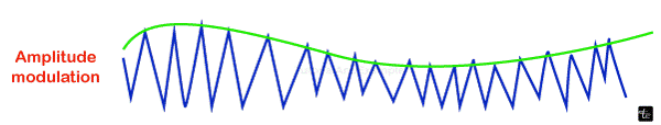
The strength of the signal transmitted by the carrier is adjusted with this modulation to denote binary 1 and 0. While the amplitude fluctuates, the frequency and phase stay constant. It is up to system designers to determine which voltage represents 1 and which value represents 0. The bit duration is the period of time that constitutes a bit. The peak amplitude of the signal is constant for each bit length, and its value is determined by the number of bits (0 or 1). The physical features of the carrier medium restrict the transmission speed while employing ASK.
However, ASK transmission is prone to noise interference. Remember that noise is the purposeful voltages put into a line by different phenomena like as heating or electromagnetic induction, which are caused by other sources.
These unintended voltages interact with the signal, changing its amplitude. A 0 may become a 1, and a 1 can become a 0. As you can see, noise is particularly difficult to detect with ASK, which depends exclusively on amplitude for identification. Because noise often influences amplitude, ASK is the modification technique most impacted by noise.
Frequency Shift Modulation (FSK)
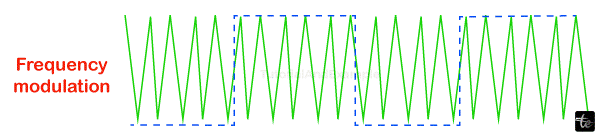
The speed of a carrier signal varies in this form of modulation to represent decimal 1 and 0. The signal's frequency remains constant over the bit length, and its value is determined by the number of bits (0 or 1): all the amplitude of the peak and phase stay constant.
FSK avoids the most of the ASK's noise issues. Disregard the voltage peaks since the receiving equipment is seeking for particular frequencies changes in a specific number of periods. The physical abilities provided by the carrier are the elements that restrict FSK.
When an audio wave undergoes modulation with a radio frequencies carrier signal, the frequency level of the resulting frequency signal is changed. It is important to watch how the wave flows upward and downward. This is known as deviation, and it is usually expressed in kHz.
For example, if a signal has a variation of + or - 3kHz, it appears as 3kHz. This signifies that a carrier signal has a 3kHz up and down deviation.
Broadcasting stations that require an extremely high frequency band in the radio spectrum (in a range of 88.5 - 108 MHz) require a significant amount of deviation (almost 75 kHz). This is referred to as wide-band frequency modulation. All signals within this range of frequencies are stable.
The following are the many forms of frequency modulation:
FM narrow band
- This is the sort of frequency modulation in which the modulation index is too low.
- Whenever the modulation index is 0.3, there will be a single carrier and matching sidebands with a bandwidth twice that of the modulating signal. As a result, 0.3 is referred to as narrow band modulation of frequencies.
- The maximum modulating frequency range is 3 kHz.
- 75 kHz is the highest frequency deviation value.
FM frequency range
- This is the form of frequency modulation in which the modulation index's value is high.
- When the index of modulation is more than 0.3, there can be a maximum of two side bands with bandwidth equal to twice the signal that is being modulated. The number of side bands grows as the modulation index's value increases. As a result, > 0.3 is referred to as narrow range frequency modulation.
- The maximum modulating frequency range is between 30 Hz and 15 kHz.
- 75 kHz is the top frequency deviation value.
- This frequency modulation requires a wider bandwidth range, which is about 15 times more than that of narrow band modulation on frequencies.
Phase Shift Modulation (PSK)
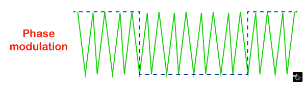
The carrier's phase changes in PSK modulation serve as a value of 1 or 0. While the phase varies, the peak frequency and amplitude stay constant. For instance, if you begin with the phase of zero degrees representing the binary 0, you may modify it to 180 degrees in order to communicate a binary 1. The signal's phase remains constant during the period of each bit, and its value is determined by the value of that bit (0 or 1). The diagram is a conceptual representation of PSK.
Because two separate stages (0 and 180 degree) are employed, the aforementioned approach is commonly referred to as 2-PSK, 0 binary PSK. The diagram illustrates this topic by demonstrating the link between phase and decimal value. A second diagram, known as a constellations or a phase-state graph, depicts the same connection but only shows the phases.
PSK is not affected by noise degradation, which impacts ASK and FSK band restrictions. It means that little fluctuations in the signal may be consistently recognized in the receiver. In addition to employing simply two signal variants, each indicating one bit, you may use four variations, each representing two bits.
Quadrature Amplitude Modulation (QAM)
PSK is restricted by teams' ability to discern slight variations in phase. This factor restricts your maximum bit rate.
So far, only one of the three sine wave qualities has been changed at one point, but what occurs if two are changed? The combination of FSK alongside additional modifications is rendered largely ineffective due to bandwidth constraints. But why not mix ASK with PSK? In such situation, we may have x phase and amplitude variations, offering us multiples of x and potential variations, as well as the equivalent amount of bytes per variation. QAM (quadrature amplitude modulation) does this. Quadrature is generated from the constraints required for minimal performance and is connected to trigonometry.
Quadrature amplitude modulation (QAM) is the combination of ASK and PSK to maximize the contrast between each bit, debit cards, tibit, quadbit, and so on. The graph depicts two potential combinations: 4-QAM and 8-QAM.
Modulation Applications of Various Types
- There are several modulation techniques available, including:
- Music mixing and magnetic tape recordings systems use it.
- To keep track of EEG monitoring for newborns
- Used in telemetry, radar, and FM broadcasting techniques
Advantages of Modulation
Modulation has the following advantages:
- It minimizes the size of an antenna.
- It lowers the cost of wiring.
- It makes signal mixing illegal.
- It broadens the scope of communication.
- It enhances reception quality.
- The signals are readily multiplexed.
- It also enables for bandwidth modification.
Disadvantages of Modulation
Modulation has the following disadvantage:
- Being more expensive in terms of equipment.
- Both the receiver that receives and its transmitter are quite complex.
- The FM system antennae must be kept covered for optimum connection.
- It is inefficient when dealing with big amounts of bandwidth.
- There is power waste.
Conclusion
In conclusion, because low-frequency signals cannot be sent over long distances, modulation is essential for signal transmission. Modulation is also crucial for allocating extra channels to consumers and increasing noise immunity.