ER Diagram for Banking System in DBMS
Entity Relationship Diagram
Entity Relationship Diagrams, or ER Diagrams for short, are diagrams that show the relationships among entity sets that are stored in databases. Alternatively said, ER diagrams assist in describing the logical layout of databases. Entities, attributes, and relationships are the three fundamental ideas on which ER diagrams are based. Entities, traits, and relationships are all represented as rectangles, ovals, and diamond shapes in ER diagrams.
At first impression, a flowchart and an ER diagram are similar. The ER Diagram is a particular model, nevertheless, because of the multiple specific symbols and their associated meanings. The entity framework architecture is shown in the ER Diagram. The relationship between the entities that will be recorded in a database is shown in an entity relationship diagram (ER Diagram). The ER Diagram illustrates how a database is structured. With the aid of specialized symbols, it serves as a foundation for defining the connections between database entities. Entities, attributes, and relationships make up the core three elements of an ER diagram.
The relationship between the objects Student and Course is depicted in the diagram below. A student and a course have a many-to-many relationship since different students may choose the same course and a student may choose multiple courses. Stu Id, Stu Name, and Stu Age are characteristics of the student object. Aspects of the course object include Cou ID and Cou Name.
Entity Relationship Diagram of Bank
The ER diagram of Bank is described as follows:
- Bank has clients.
- Names, codes, and the main office address are used to identify banks.
- The branches of banks.
- Branch no., Branch name, and Branch Address are used to identify branches.
- Name, customer ID, phone number, and address are used to identify customers.
- One or more accounts may be open for a customer.
- The account no., acc type, and amount are used to identify accounts.
- Customers may apply for loans.
- The loan id, loan type, and amount are used to identify loans.
- Loans and accounts are connected to the bank branch.
ER Diagram for Banking System:
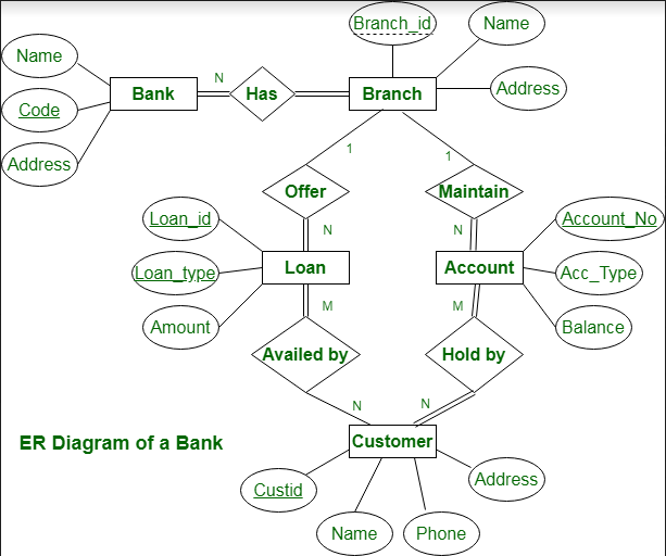
This bank ER diagram shows important details about the bank, including things like branches, clients, accounts, and loans. It enables us to comprehend the connections between various elements.
Entities and their Characteristics:
- Bank entity:Bank Name, Bank Code, and Bank Address are characteristics of a bank entity.
Code is the Bank Entity's Primary Key.
- Customer entity:Customer id, Name, Phone Number, and Address are the attributes of a customer entity.
The primary key for the customer entity is customer_id.
- Branch entity:Branch id, Name, and Address are the attributes of a branch entity.
The Branch Entity's Primary Key is Branch id.
- Account Entity: Account number, Account Type, and Balance are its attributes.
The primary key for the account entity is account number.
- Loan Entity: Loan id, Loan Type, and Amount are its attributes.
The primary key for the loan entity is loan id.
In relationships, and Branch are related one to many.
Branches of the Bank = >1: N
A branch cannot be a member of more than one bank at a time, hence the relationship between a bank and a branch is one to many.
Maintain branch accounts => 1: N
One Account cannot belong to many Branches, whereas one Branch may have numerous Accounts. As a result, the connection between a Branch and an Account is one to many.
Branch Loan Offers =>1: N
One Loan cannot belong to more than one Branch, hence the relationship between a Branch and a Loan is one to many in nature.
Customers' account balance => M: N
The relationship between an account and a customer is one of many to many since one customer may hold multiple accounts in addition to one account being held by one or more customers.
Loan taken out by the customer = >M: N (Assume loan can be jointly held by many Customers).
One customer may have multiple loans, and one loan may be used by one or more customers, hence there is a many-to-many relationship between loans and customers.
Conclusion
Entity Relationship Diagrams, or ER Diagrams for short, are diagrams that show the relationships among entity sets that are stored in databases. Alternatively said, ER diagrams assist in describing the logical layout of databases.
Entities, attributes, and relationships are the three fundamental ideas on which ER diagrams are based. Entities, traits, and relationships are all represented as rectangles, ovals, and diamond shapes in ER diagrams.