
Micro-Operations
Micro-Operations
If CPU wants to perform any operation, suppose execution of only one instruction or even break it down one particular execution phase (like fetch instruction, write back, decode, operand fetch etc.). CPU cannot perform one operation in one single step; it performs these operations in multiple small- small steps. These small-small steps of operations are called micro-operations.
Definition-“The operations executed on values stored in registers are called as micro-operations." CPU can perform operations on some values (operands), and these values are stored in memory(registers). Operations made by the CPU to fetch these values and execute the instruction are micro- operations.
“To execute an instruction or program CPU perform various operations step by step and these instructions are commanded by the control unit of the CPU. Control unit generate command and rest of the system follow these commands to fetch the instruction. Whenever one type of command is generated by your control unit then a particular small operation is performed and that operation is micro-operation.”
The language used to perform micro-operation.
Let's say CPU wants to perform this micro-operation “Copy content of program counter into address register”.
This is one of the requirements CPU wants to perform, but we cannot write this lengthy operation like this, and it is not understandable by the CPU. To denote all these micro-operation, scientists have given a notational language called R.T.L. ( Register Transfer Language).
"Register Transfer Language provides symbolic notation to describe the micro-operation." Register transfer language makes it easy to denote micro-operation in the CPU. For example, Micro-operation like "Copy content of program counter into address register" can be denoted as ARß PC. But register transfer language is just a symbolic language; it is not executed anywhere. There is no compiler or assembler for RTL; it's just a notational symbolic language.
The way how micro-operations denoted in RTL(register transfer language)
- Register Transfer: It can be written like R1 ßR2, or R2ß R1
- Comma: If two micro-operations are written and separated by a comma, it means that both the micro-operations can be performed simultaneously. There are some chances where CPU can perform operations simultaneously; these can be written like this:
R1ß R2+ R3, PC ß PC +1
- Memory transfer: Memory transfer consists of two operations that are memory read, and memory write operation.
In-memory read operation, data is transferred from memory towards CPU (CPUß memory), but it is not possible that entire memory content goes to CPU. Specific content is brought by memory to CPU by fetching that specific address where content is stored in the memory, and we can write instruction like this:-
R1ß M[address] or R1ß M[2000] or R1ß M[A.R.]
In a memory write operation, data is transferred from CPU to memory (Memoryß CPU). Here also, we have to specify the address where data is written in memory. We can write instruction like this:-
M[address]ß R1 or M[1000]ß R1 M[AR]ß R1
Types of Micro-operations
- Arithmetic Micro-operations
- Logic Micro-Operations
- Shift Micro-operations
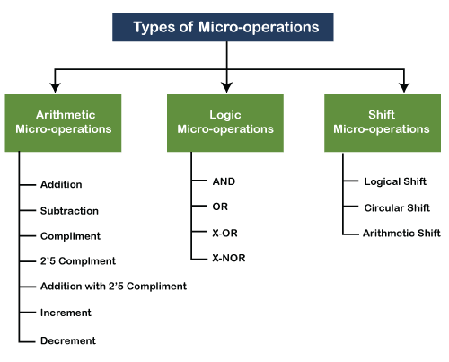
- Arithmetic Micro-operation – In CPU, arithmetic logic unit(ALU) perform various operations, and they can be denoted like this:-
- Addition: The two operands are stored in different registers, and after addition, the function result is stored in another register.
R1ß R2 + R3
- Subtraction: In subtraction, two operands are stored in different registers, and after subtraction, the function result is stored in another register.
R1ß R2 - R3
- Compliment: Compliment means every bit of R2 register is flipped 1à0, 0à 1(1 become 0 and 0 becomes 1)
R1 ß R?2?
- 2's complement: 2's compliment is the addition of 1 in the 1's complement of R2 and copy back to R1
R1 ß R?2? + 1
- In addition to 2's compliment: It is adding R2 with 2's complement of R3 with one and copies it to R1.
R1 ßR2 + R?3? + 1
Note: basically, taking 2's compliment means the negation of the number.
2’s compliment of 10 = -10( it denotes that number becomes negative after 2's compliment); therefore, the above statement can be written as:
R1ß R2 – R3
- Increment – It is just an addition of 1 in R1( increase the value by one).
R1ßR1 +1
- Decrement- It is just a subtraction of 1 in R1( decrease the value by one).
R1ßR1 +1
- Logic Micro-operations – Logic micro-operations are working of few logic gates. Logic gates are used to implement the Boolean function, and gates are the circuits that can allow or cannot allow current to pass through them. If current passes, it gives value 1, otherwise it gives value 0. There are four types of logic micro-operations and denoted like this:-
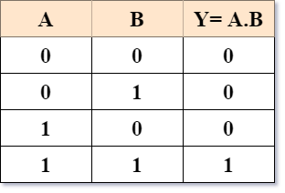
- AND – AND gate is known as a series circuit. R2 and R3 contain two inputs, and the result is stored in R1.
R1ßR2^ R3
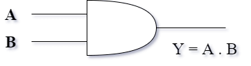
AND Gate Truth table
- OR – OR gate, we use the disjunction symbol. Two inputs are stored in R2 and R3 register, and the result is stored in R1.
R1ßR2 ? R3
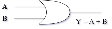
OR Gate Truth table
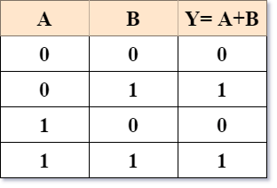
- X-OR – It is like an OR gate, but excluding both inputs are true. X-OR gate has two inputs in two registers, and the result is stored in R1.
R1ßR2? R3
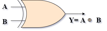
X-OR Gate Truth table
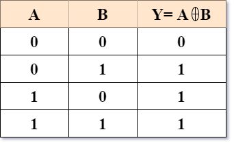
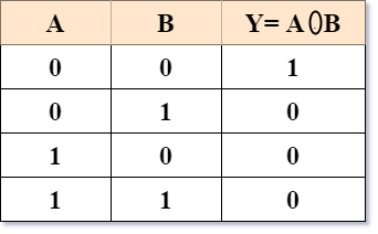
- X-NOR- This is an X-OR gate with an inverted output. X-NOR gate has two inputs in two registers, and the result is stored in R1.
R1ßR2? R3
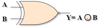
X-NOR Gate Truth table
- Shift Micro-operations – There are three types of shift micro-operations and denoted like this:-
- Logical shift
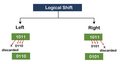
The logic shift means that we have to shift digits logically from one place to another place. It is of two types:- Left shift or Right shift.
Left shift:- let suppose a register has 4 bit 1011, and if we shift this value to left, then the left-most digit is discarded and remaining three are shifted to the left, and the new digit 0 is added to the number (remember that always 0 is added as a new digit). Now a new number is 0110 after left shift.
1011à 0110
Right-shift - let suppose a register has 4 bit 1011. If we shift this value to the right, then the rightmost digit is discarded, and remaining three are shifted to the right, and the new digit 0 is added to the number (remember that always 0 is added as a new digit). Now a new number is 1010 after the right shift.
1011à 1010
- Circular Shift
As the name defined, circular means circle or in rotation. Here digits are not discarded; they are shifted in a circular motion. The circular shift is also of two types:- Left circular shift and Right circular shift.
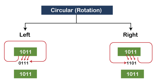
Left circular shift:- let suppose a register has 4 bit 1011, and if we shift this value in circular, then the left-most digit is not discarded. It is shifted to the rightmost corner, and the remaining three are shifted to the left. Now a new number is 0111 in the register after applying the left circular shift.
1011à 0111
Right circular shift:- let suppose a register has 4 bit 1011, and if we shift this value in circular, then the rightmost digit is not discarded; it is shifted to a left most corner, and the remaining three are shifted to the right. Now a new number is 1101 in the register after the right circular shift.
1011à1101
- Arithmetic Shift – The arithmetic shift is applied to signed values or signed numbers. There is a constraint in an arithmetic shift that whether it is left shift or right shift on any number which is a signed number then after the shift the signed should remain same. If arithmetic left or right shift is applied to the positive number, it remains positive after the shift. If the initial number is negative, then after shifting, the answer remains negative.
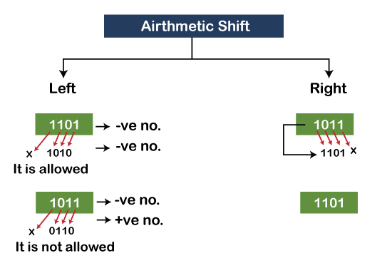
Left arithmetic shift: It is the same as a logical left shift, but it is allowed only when the sign is not going to change. If left arithmetic shift is applied on a negative number then after shifting that number, answer comes negative, it is allowed by CPU and in other case too if the number is positive and after shifting that number, answer comes negative, in some cases it is also not allowed by CPU.
For example: Suppose the number is 1101(-ve number due to M.S.B. is 1)
1101 à 1010 (-ve number)
So, it is allowed but let's take another number, 1011(-ve number), apply shift on this number. 1011à 0110(+ve number)
Now, 0110 is positive because the M.S.B. bit is 0. CPU does not process arithmetic left shift on this number. CPU gives an error named Arithmetic left shift overflow. Therefore a number on which arithmetic left shift is not allowed generates an error called arithmetic left shift overflow.
Right arithmetic shift: let suppose a register has 4-bit 1011 number and it's a negative number as M.S.B. of number is 1. If we shift this value, the rightmost digit is discarded, the remaining three digits are shifted to the right, and to maintain the sign(negative or positive) of number the left-most digit is copied as M.S.B. ( same to same). Now the result after the right arithmetic shift is 1101. 1011à 1101