Color Models in Computer Graphics

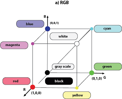
"Color model is a 3D color coordinate system to produce all range of color through the primary color set." There are millions of colors used in computer graphics. The light displays the color. A Color model is a hierarchical system in which we can create every color by using RGB (Red, Green, Blue) and CMYK (Cyan, Magenta, Yellow, Black) models. We can use different colors for various purposes.

The total number of colors displayed by the monitor depends on the storage capacity of the video controller card.

The Video controller card is used as an interface between the computer system and the display device. It is also known as “Video Random Access Memory (VRAM).”

Types of Color Model

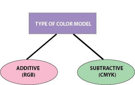
The basic color model is divided into two parts-
Color Model
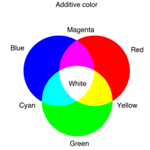
  • Additive Color Model: It is also named as “RGB model.” RGB stands for Red, Green, Blue. The Additive color model uses a mixture of light to display colors. The perceived color depends on the transmission of light. It is used in digital media.

For Example- Computer Monitor, Television etc.
Color Model 1
Color Model 2
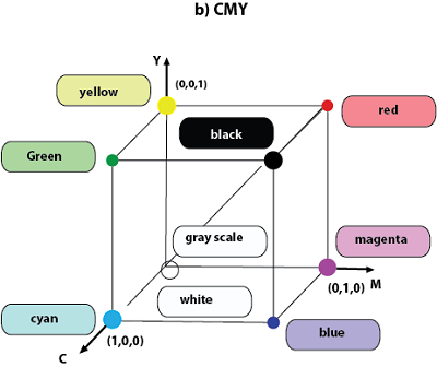
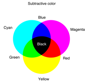
  • Subtractive Color Model: It is also named as “CMYK Model.” CMYK stands for Cyan, Magenta, Yellow, and Black. The Subtractive model uses a reflection of light to display the colors. The perceived color depends on the reflection of light.

The CMYK model uses printing inks.

For Example- Paint, Pigments, and color filter etc.
Color Model 3
Color Model 4

Advantages:

  1. Easy to Implement.
  2. It uses color space for applications.
  3. No transformation for data display.

Disadvantages:

  1. We cannot transfer the color values from one to another device.
  2. Complex to determine the particular color.

Color Look-Up Table

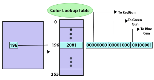
The color Look Up table is a technique or process to convert a range of input colors into another range of colors. It is also called as “CLUT.” The color Lookup table has existed in the graphics card. Graphics Card is also called “Display Adapter.” The Color Look-Up table provides us various colors that are used to modify the color of the objects. Either we can use the colors available in the palette, or we can create the colors of our choice in the color window.

In image processing, the lookup table is used to change the input into the more required output format. The Color Look-Up table is used to store and index the color value of an image.
Color Model 5

Look Up File: The Look-Up file is a two-dimensional table that is used to contain the data. The Look Up data is stored in a disk file.

Color Palettes: The color palettes are defined as mathematical tables used to determine the color of the pixel that is displayed on the screen.

In the Macintosh Operating system, it is known as “Color Look-Up table.”

In Windows operating system, it is known as the “Color palette.”

It is used to stores a set of bytes instead of the color of the image.

Advantages:

  1. Easy to modify.
  2. Space Efficient.

Disadvantages:

  1. It does not maintain any changes in the history.
  2. There is a need to determine and maintain the reference.

Direct Coding

Direct Coding is a technique or process which is used to provide a certain amount of memory storage space for a pixel to encode the pixel with the color.

For Example- If we assign one bit for each primary color to 3-bit for each pixel. This 3-bit representation allows the two intensity levels of each primary to separate: 0(Off) or 1(On),then each pixel can occupy one color out of eight colors that are similar to the corner of the RGB color cube.

Bit1: Red Bit2: Green Bit: Blue Color Name
0 0 0 Black
0 0 1 Blue
0 1 0 Green
0 1 1 Cyan
1 0 0 Red
1 0 1 Magenta
1 1 0 Yellow
1 1 1 White

Mostly 3 bytes, or 24 bits per pixel are used in industries and companies, with 1 byte for each primary color. We can allot each primary color to have 265 different intensity levels, similar to binary values from 00000000 to 11111111.

The color of the pixel can be 265 x 265 x 265 or 16.7 million. The representation of black and white, the grayscale image, needs just 1 bit per pixel. The bit value 0 represents black, and 1 represents white. The direct coding technique is simple, and it also supports various applications.


Related Topics

2D Scaling

In scaling, we can expend or compress the size of any object. We can apply scaling on the object by multiplying the original coordinates with scaling factors. The term scaling factor...

2 minutes read.

Homogenous Coordinates in Computer Graphics

Homogenous Coordinates in Computer Graphics The orbit of a point, a line graph or the whole picture on the computer, a point besides the origin, is accomplished by first shifting the...

7 minutes read.

Point Clipping

“Point clipping is a process which is used to define the point position.” The point is either inside the view pane (window) or outside the view pane. In computer graphics, the computer...

2 minutes read.

Composite Transformation in Computer Graphics

Composite transformation in Computer Graphics It is possible to integrate a range of transformations or series of transformations into some kind of a single one which is known as composition. The...

6 minutes read.

Display Processor

It is a part of hardware or interpreter which is used to transform display processor code into pictures. It is used to convert digital information from CPU to analog data. It...

4 minutes read.

Mid-Point Line Drawing Algorithm in Computer Graphics

The Mid-point Subdivision algorithm is the extension of the Cyrus-Beck algorithm. The Mid-Point line plotting algorithm was introduced by “Pitway and Van Aken.” It is an incremental line drawing algorithm....

8 minutes read.

Anti-aliasing in Computer Graphics

Anti-aliasing in Computer Graphics “Anti-aliasing is a method for eliminating the aliasing effect used in computer graphics. In a 2-dimensional object, the ambient occlusion impact is the existence of sharp edges...

7 minutes read.

Scan Conversion of an Ellipse Computer Graphics

Scan Conversion of an Ellipse: An ellipse can be defined as a closed plane curve, which is a collection of points. It is the cause of the intersection of a...

8 minutes read.

DDA line Drawing Algorithm in Computer Graphics

DDA (Digital Differential Analyzer) Line Drawing Algorithm The Digital Differential Analyzer helps us to interpolate the variables on an interval from one point to another point. We can use the digital Differential Analyzer algorithm...

5 minutes read.

Polygon Clipping in Computer Graphics

“A Polygon can be described as the enclosed collection or group of the lines.” In a polygon, all lines are connected. Lines can be a combination of edges and vertices,...

4 minutes read.

Zooming

In computer graphics, the term “Zoom is referred as a function, focuses on a particular portion or part of an image and also enlarging the image’s size for greater details.” In windows...

2 minutes read.

Projection in Computer Graphics

Projection Introduction: The technique projection was invented by the Swiss mathematician, engineer, and astronomer "Leonhard Euler Around" in 1756. The "Episcope" was the first projection system. “Projection is a technique or process which...

4 minutes read.

Input Devices in Computer Graphics

An Input device is the piece of computer hardware equipment used to give input to the computer. The input can be in the form of graphics, text, sound, audio, video,...

7 minutes read.

2D Transformation in Computer Graphics

Some visuals are transformed into some other graphics by implementing several of the principles known as transformation. There are multiple kinds of transformation, including translation, scaling, rotation, shearing, etc. Whenever...

2 minutes read.

History of Computer Graphics

History of Computer Graphics Computer Graphics (CG) was first developed as a visualization tool. Computer graphics were basically introduced for scientists and engineers in government and corporate research centers, i.e., Bell Labs and Boeing...

4 minutes read.

Bresenham’s Line Drawing Algorithm in Computer Graphics

This algorithm was introduced by “Jack Elton Bresenham” in 1962. This algorithm helps us to perform scan conversion of a line. It is a powerful, useful, and accurate method. We...

8 minutes read.

3D Shearing

We can denote shearing with ‘SHx,’ ‘SHy,’ and ‘SHz.’ These ‘SHx,’ ‘SHy,’ ‘SHz’ are called “Shearing factor.” The basic difference between 2D and 3D Shearing is that the 3D plane also...

1 minute read.

Applications of Computer Graphics

Applications of Computer Graphics Some applications of computer graphics are mentioned below- Graphical User Interface (GUI): It is a way of interacting with a computer using the icon, ...

2 minutes read.

Output Devices in Computer Graphics

Computer Graphics Output Devices An output device is a component of hardware or the main physical part of a computer that can be touched and seen. An output device is an electromechanical device. “The...

5 minutes read.

Panning

“Panning is a process or photographic technique that is used to combine slow shutter speed with camera movement to make a speed sense around the moving object.” We can define panning as...

2 minutes read.