3-bit Full Adder in Digital Electronics
Full Adder
A full adder is a digital logic circuit that performs the addition of two binary numbers. In the case of a 3-bit full adder, the circuit is capable of adding three binary inputs (A, B, and C) and generating two outputs: a sum (S) and a carry (Cout).
A full adder is a combinational logic circuit that adds three binary inputs: two single-bit numbers (A and B) and a carry-in (Cin) from a previous bit position. The full adder generates two outputs: a sum (S) and a carry-out (Cout), which can be used as the carry-in for the next bit position in a multi-bit addition.
The sum output (S) is generated by taking the modulo-2 sum of the inputs (A, B, and Cin), while the carry-out (Cout) is generated when the sum of the inputs is greater than The full adder can be implemented using basic digital logic gates, such as AND, OR, and XOR gates, or using more complex circuits, such as multiplexers or lookup tables.
The full adder is a building block for more complex digital circuits, such as adder-subtractors, arithmetic logic units (ALUs), and many other digital systems.
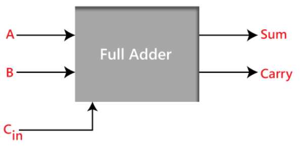
Block Diagram for a 3-bit Full adder
Truth Table
Here's the truth table for a 3-bit full adder:
| A | B | Cin | S | Cout |
| 0 | 0 | 0 | 0 | 0 |
| 0 | 0 | 1 | 1 | 0 |
| 0 | 1 | 0 | 1 | 0 |
| 0 | 1 | 1 | 0 | 1 |
| 1 | 0 | 0 | 1 | 0 |
| 1 | 0 | 1 | 0 | 1 |
| 1 | 1 | 0 | 0 | 1 |
| 1 | 1 | 1 | 1 | 1 |
In the above table,
- "A" and "B" are the input variables. These variables represent the two significant bits which are going to be added
- "Cin" is the third input, which represents the carry. The carry bit is retrieved from the previous lower significant position.
- The "sum" and "carry" are the output variables that define the output values.
- The eight rows under the input variable represent all possible 0 and 1 combinations that can occur in these variables.
In a 3-bit full adder, the carry-in (Cin) is the carry-out (Cout) from the previous bit position, and the sum (S) is the result of the current bit addition.
The 3-bit full adder can be implemented using individual 1-bit full adders, with the carry-out from one full adder connected to the carry-in of the next. The output of the final full adder will be the sum (S) and carry (Cout) of the 3-bit addition.
3-Bit Full adder using K-Map
With the help of the K-map, you can get the SOP form as follows:
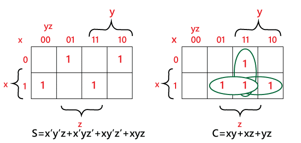
Sum = x'y'z+x'yz+xy'z'+xyz
Carry = xy+xz+yz
Logic Gate Implementation
The "AND" and "XOR" gates can be combined with an "OR" gate to create the complete adder logic circuit.
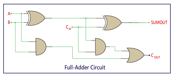
The Boolean expression for the full adder can be derived from the logic of the circuit.
The sum output (S) is obtained by performing the XOR operation of the inputs A and B, and then performing another XOR operation with the carry-in (Cin). This can be represented as:
S = (A ⊕ B) ⊕ Cin
The carry-out (Cout) is obtained by first performing the AND operation of the inputs A and B, and then performing the XOR operation of the inputs. Finally, the OR operation of the two outputs is performed to get the carry-out. This can be represented as:
Cout = A.B + (A ⊕ B)
These Boolean expressions can be used to implement the full adder using digital logic gates, such as AND, OR, and XOR gates, or can be implemented using other digital circuits, such as lookup tables or multiplexers.
How to Make a Full Adder Circuit:
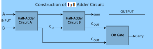
The Full adder circuit's construction is depicted in the above block diagram. The OR gate is used to combine two half adder circuits in the above circuit. We already know that the first half adder produces Sum and Carry from its two single-bit binary inputs, A and B. The first adder's "Sum" output will serve as the second half adder's first input, and the first adder's "Carry" output will serve as the second half adder's second input. "Sum" and "Carry" will once more be provided by the second half adder. The "Sum" bit is the final product of the Full adder circuit. We feed the first and second adder's "Carry" outputs into the OR gate in order to determine the carry's final output. The final carryout of the complete adder circuit will be the output of the OR gate.