Oscilloscope
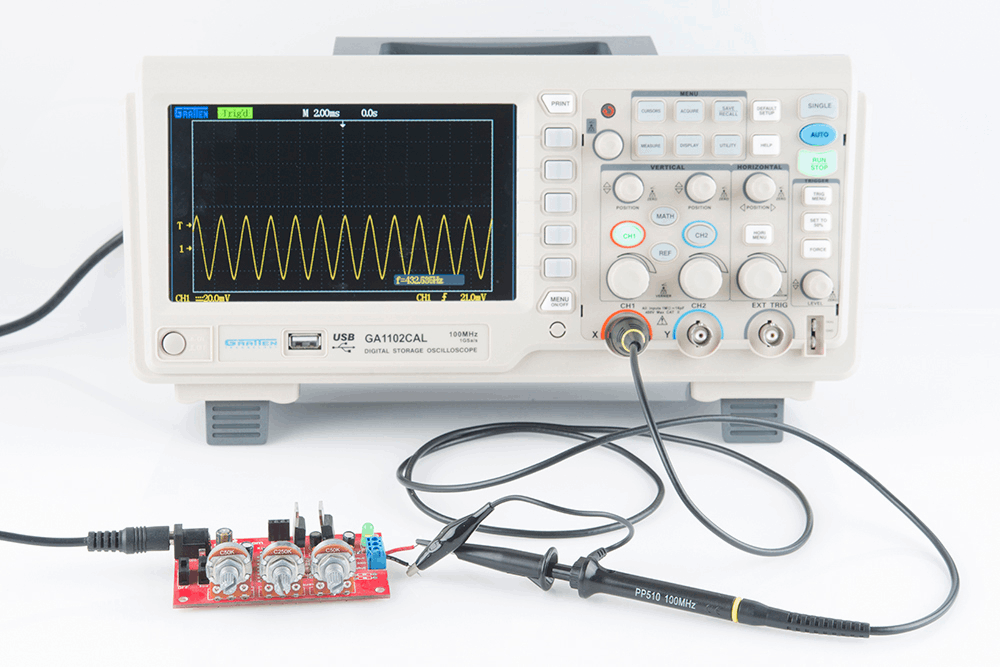
With the use of an oscilloscope, you may observe the waveform of electronic signals and the changes in voltage over time.
Why is that crucial?
Circuits are required to transmit electrical energy to electronics devices like lights, TVs, and air conditioning. A loop is a channel that a current travels through that connects two or more places. Voltage is the amount of electrical force that drives a current between two points. You sometimes need to figure out where the voltage is acting improperly in order to repair it, and in such cases, we need an oscilloscope. So firstly, lets discuss what is an Oscilloscope?
What is an Oscilloscope?
When you have circuits with consistent voltages, a multimeter is a tool that may be used to measure a single number for the voltage. This is not required when building circuits that are more complex. In circumstances like this, an oscilloscope is helpful.
You may observe the evolution of voltage with an oscilloscope. These voltages, which are utilized to carry information, are referred to as signals. An audio signal, for example, plays music on a loudspeaker. A graph representing the measured voltage signal is one of the things an oscilloscope's display screen can display. The vertical axis shows the voltage, and the horizontal axis shows the time.
Additionally, it will enable you to find any issues with your circuit, such as noise or unexpected signals. Analog and digital oscilloscopes are the two different sorts. We will review the oscilloscope's brief history today, and we will talk more about that later.
A Synopsis of Oscilloscope History
French physicist André Blondel created the oscilloscope in 1893. The electrical quantities, including such alternative current intensity, might be recorded by his gadget. The information was recorded on a rolling paper tape by an ink pendulum that was connected to a coil. The initial oscilloscopes' bandwidth, which ranged from 10 to 19 kHz, was incredibly tiny.
When German physicist Karl Ferdinand Braun created the cathode ray tube in 1897, significant advancements occurred (CRT). After World War2, oscilloscope development accelerated.
Two individuals, Howard Vollum and Melvin Jack Murdock, started Tektronix in 1946; now, it is one of the world's top manufacturers of oscilloscopes. They developed the model 511 oscilloscope, having triggered sweep and 10 MHz bandwidth, in the same year. A repeating waveform could be displayed stationary thanks to triggered sweep.
An Analog oscilloscope: what is it?
Analog oscilloscopes use high gain amplifiers to display the waveform on a green cathode ray tube (CRT) display. Analog oscilloscopes, to put it simply, are the earlier iteration of an oscilloscope that was created in the 1940s. A horizontal channel, one or more vertical channels, a trigger mechanism, a time basis, and a CRT module are all included with an analogue oscilloscope.
An attenuator, preamplifier, analogue delay line, and vertical amplifier are all components of a vertical channel that amplifies a signal to the necessary level for the CRT model. There are two working modes for horizontal channels: internal and external. Level adjustments in trigger systems alternate between increasing and lowering levels.
A Digital oscilloscope: what is it?
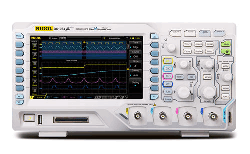
Modern LCD screens are used in digital oscilloscopes. Modern oscilloscopes are almost exclusively produced as digital devices. The signal is processed further on a digital oscilloscope before being shown on the screen. CRT-style panels are not necessary because of the additional step that transforms the signal into a digital stream using an analogue to digital converter. This makes the design simpler and makes way for more features.
An illustration would be the inclusion of complicated mathematical operations and signal manipulation, which are now typical capabilities for the majority of digital oscilloscopes.
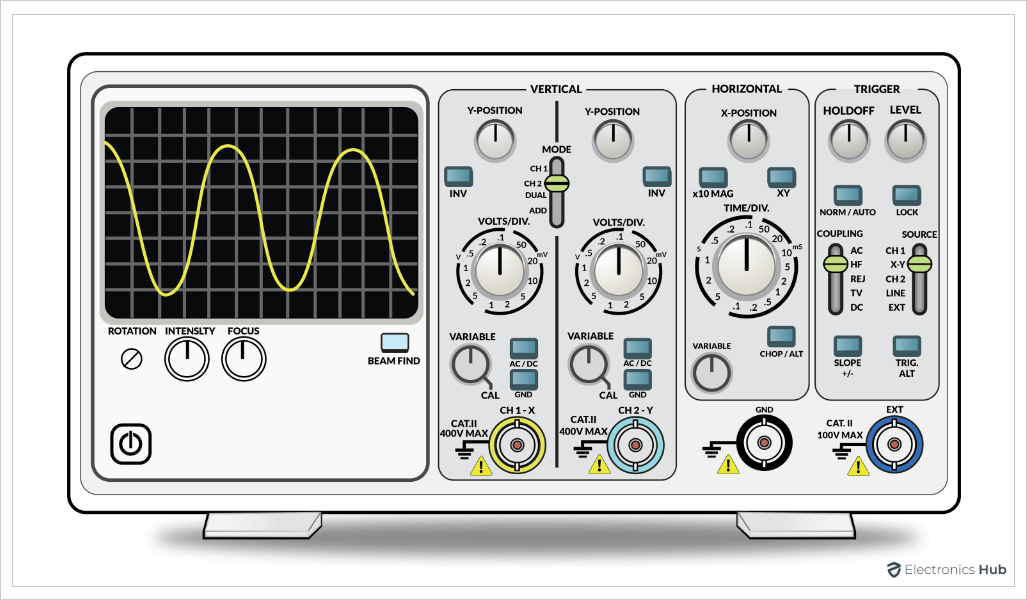
What purpose do the Systems Serve on an Oscilloscope?
The vertical, horizontal, trigger, and display systems are the four distinct systems that make up an oscilloscope in its most basic form. With each of these systems, you can measure particular things.
The waveform can be scaled and positioned vertically using the controls for the vertical system. Additionally, it can be used to control input coupling, bandwidth augmentation, and bandwidth limits. In addition to locating and horizontally scaling the waveform, the horizontal system can be utilized to determine the sampling frequency and record length.
The trigger system enables you to effectively capture a photograph of the waveform while stabilizing repeating waveforms. There are various trigger system types that react to particular situations in the incoming signal, such as edge triggering and threshold triggering.