Full Subtractor using Decoder in Digital Electronics
A full subtractor is a combinational circuit that performs subtraction of two binary numbers. It is a type of digital circuit that takes two binary numbers as inputs and produces the difference between them as its output. The full subtractor is an important component in many digital systems, as it is used to perform arithmetic operations such as addition, subtraction, and comparison.
The full subtractor has three inputs: the minuend (A), the subtrahend (B), and a borrow-in (Bin). The minuend and subtrahend are binary numbers, and the borrow-in is a signal that indicates whether a previous subtraction operation resulted in a borrow. The full subtractor has two outputs: the difference (D) and the borrow-out (Bout). The difference is the result of the subtraction operation, and the borrow-out is a signal indicating whether a borrow was required in the current subtraction operation.

Fig 1.1 Full Subtractor
Full Subtractor Truth Table
The truth table of a full subtractor is a table that lists all the possible input combinations and their corresponding outputs. The truth table is used to determine the behavior of a digital circuit for all possible input combinations. The truth table for a full subtractor is as follows:
| A | B | B_in | D | B_out |
| 0 | 0 | 0 | 0 | 0 |
| 0 | 0 | 1 | 1 | 1 |
| 0 | 1 | 0 | 1 | 1 |
| 0 | 1 | 1 | 0 | 1 |
| 1 | 0 | 0 | 1 | 0 |
| 1 | 0 | 1 | 0 | 0 |
| 1 | 1 | 0 | 0 | 0 |
| 1 | 1 | 1 | 1 | 1 |
Full Subtractor using Decoder
The theory behind the full subtractor implementation using a 3-to-8 decoder is based on the concept of binary arithmetic. In binary arithmetic, subtraction is performed by taking the difference of two binary numbers, taking into account the carry-out from the previous subtraction operation.
The 3-to-8 decoder is used to simplify the logic operations required to perform the subtraction. The decoder generates an output signal for each of the eight possible input combinations of A, B, and Bin. By selecting the appropriate output signal based on the inputs, the decoder reduces the number of gates required to implement the full subtractor.
The AND gates perform the logic operations required to compute the difference (D) and borrow-out (Bout) signals. The AND gates are connected in such a way that the appropriate output is selected based on the inputs. The OR gates are used to generate the final outputs, which are the difference (D) and borrow-out (Bout) signals.
In this implementation, the 3-to-8 decoder, AND gates, and OR gates work together to perform the binary subtraction operation. By selecting the appropriate output from the 3-to-8 decoder, the AND gates perform the required logic operations to compute the difference and borrow-out signals. The OR gates are used to generate the final outputs, which are the difference and borrow-out signals.
In summary, the theory behind the full subtractor implementation using a 3-to-8 decoder is based on the concepts of binary arithmetic and digital logic design. By using a decoder, the logic operations required to perform the subtraction are simplified, making the circuit more efficient and easier to design.
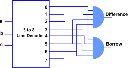
Fig 1.2 Full Subtractor using decoder
Advantages of Full Subtractor using 3-to-8 decoder
There are several advantages of implementing a full subtractor using a 3-to-8 decoder:
- Reduced gate count: By using a 3-to-8 decoder, the number of gates required to implement the full subtractor is reduced, making the circuit more efficient.
- Simplified logic operations: The 3-to-8 decoder simplifies the logic operations required to perform the subtraction, making the circuit easier to design and debug.
- Improved flexibility: The 3-to-8 decoder can be easily reconfigured to perform other binary arithmetic operations, such as addition or multiplication, making it a more flexible component in a digital system.
- Improved performance: By reducing the gate count and simplifying the logic operations, the full subtractor implementation using a 3-to-8 decoder can be faster and more reliable than other implementations.
- Reduced power consumption: By using fewer gates, the full subtractor implementation using a 3-to-8 decoder consumes less power, making it more suitable for battery-powered or energy-sensitive applications.
Disadvantages of Full Subtractor 3-to-8 decoder
While the full subtractor implementation using a 3-to-8 decoder has several advantages, there are also some disadvantages to consider:
- Increased complexity: The use of a 3-to-8 decoder can make the circuit more complex, making it more difficult to design and debug.
- Increased chip area: The 3-to-8 decoder and other components required to implement the full subtractor can take up more chip area than other implementations, making it less suitable for applications with limited space.
- Limited customization: The 3-to-8 decoder is designed to perform a specific set of logic operations, and may not be suitable for applications that require custom or specialized logic.
- Increased cost: The 3-to-8 decoder and other components required to implement the full subtractor can be more expensive than other components, making the circuit more expensive to build.
- Increased power consumption: The 3-to-8 decoder and other components required to implement the full subtractor can consume more power than other components, making it less suitable for battery-powered or energy-sensitive applications.