Capacitors in DC Circuit
Capacitor & Capacitance
A capacitor is defined as any pair of conducting surfaces divided by an insulating substance. The capacitor's conducting surfaces are referred to as the plates, and the insulating substance is called the dielectric.
The capacitance of a capacitor refers to its capacity to store charge. It is specified with the letter C and is valued in Farad (F).
It has been demonstrated through tests that the charge (Q) held within a capacitor is proportional to the potential difference across it, i.e.
Q ∝ V
Q =CV
C=Q/V…..(1)
where C is a constant that refers to the capacitor's capacitance.
As a result, the capacitance of a capacitor is determined by the relationship between the charge (Q) on each capacitor plate and the potential difference (V) across this one.
The unit of capacitance is
C=Q/V
Unit of C = Coulomb/Volt=Farad
How is a capacitor able to hold a charge?
Consider a parallel plate capacitor that is switched across a V volt battery. The following explanation explains how a capacitor is charged:
Step-1: The capacitor's plates are not charged when the switch S is open.

Step 2: When the switch S is closed, the battery's positive terminal draws electrons from plate A and collects them on plate B. This has the effect of making plate A increasingly positive and plate B increasingly negative. A capacitor is being charged in this process. Capacitor charging continues until the potential difference between the capacitor and the battery voltage is equal (V).
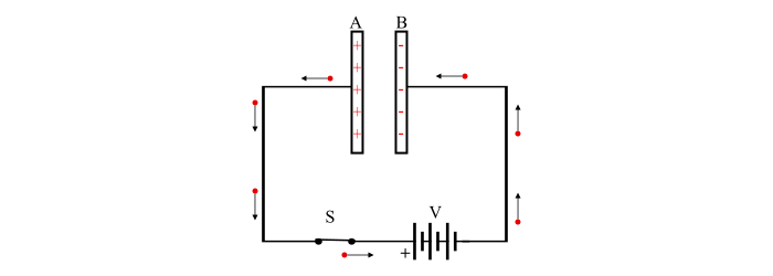
Step 3: The current flow ceases as soon as the capacitor reaches a charged battery voltage (V).

Step 4: The capacitor plates will now maintain the charge if the switch S is opened. The capacitor is therefore considered to be charged at this point.

Capacitor behavior in a DC circuit
It is possible to comprehend a capacitor's behavior in a DC circuit by considering the following:
- An uncharged capacitor is quickly (not instantly) charged to the applied voltage when a Voltage is applied across it. The source of the charging current is,
i=dQ/dt=d(CV)/dt=C dV/dt….(2)
- The voltage across the capacitor becomes equal and constant to the applied voltage when the capacitor is fully charged. Therefore, the charging current becomes (dV/dt = 0).
- In terms of DC voltage, an uncharged capacitor is equal to a short circuit because the voltage across it is zero.
- When the capacitor is fully charged, the circuit is closed off to current flow. A completely charged capacitor hence looks to dc as an open circuit.
Capacitor Charging
Consider a series resistor R connected to a battery of V volts (D.C.) to restrict the charging current within a safe range and an uncharged capacitor of capacitance C. The capacitor begins to charge when the switch S is turned closed, when a charging current runs through the circuit.

When the switch is closed, the charging current is at its highest and progressively decreases as the voltage across the capacitor rises. The charging current is lowered to zero when the capacitor is reached to applied voltage (V), which is the complete charge state.
Immediately after the switch is closed
The voltage across the capacitor is 0 when the switch is closed (as the capacitor is uncharged at the start). The resistor R is crossed by the full voltage V, and the charging current is at its highest. Therefore,
Initial Charging Current, Im= V/R
Voltage Across Capacitor,v=0
Charge On Capacitor,Q=0
Any time, at any moment, t
When the switch is closed, the charging current begins to decrease and the voltage across the capacitor steadily rises. Consequently, whenever instant t occurs,
Voltage Across Capacitor =v
Charge on capacitor =q=Cv
The Charging Current =i=C dv/dt
Voltage through the capacitor
We may write, by utilizing KCL in the circuit:
V= VR+v
=> V=iR+v=(Cdv/dt)R + v….(3)
=> dv/ V-v =dt/RC
Integrating on both sides we get,
∫ dv/V-v = ∫dt/RC
When this integration is resolved, we get,
-loge (V-v) = t/RC + K….(4)
The starting circumstances allow for the determination of K's value. When the switch is shut off, t = 0 and v = 0. Consequently, the equation (4),
-loge V = K
Replace K's value in the equation. (4) We get,
-loge (V-v) - loge (V) = -t/RC
-loge (V-v/V) = -t/RC
Apply antilog on both sides , we get,
(V-v/V) =e-t/RC….(5)
v=V(1-e-t/RC).....(6)
The eq. (5) demonstrates how the voltage across the capacitor rises exponentially while charging.
Charging current -
From eq. (3),
(V-v) =iR
And from eq. (5),
(V-v) = Ve-t/RC
iR= Ve-t/RC
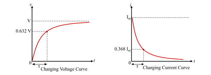
i= (V/R)e-t/RC = Im e-t/RC ….(7)
Im is the initial charging current in that situation. Additionally, it is evident from eq. (7) that charging current decreases exponentially. The graphic representation of the charging current and charging voltage is shown below.
Time Constant
The amount of time needed for the capacitor voltage (v) to increase to its final stable value, V, is the time constant. The symbol for it is Tau (T), and it is provided by,
Time Constant, T = RC seconds….(8)
Discharging of Capacitor
Take into account a charged C farad capacitor that is in series with such a resistor R via a switch S. The voltage across the capacitor is V volts when the switch is open. When the switch is shut off, a discharging current begins to flow through the circuit, which causes the capacitor to begin discharging and the voltage across it to drop. The discharging current immediately increases to a value Im before falling to zero.

Discharging voltage -
Consider at any time instant t during discharging,
Voltage Across Capacitor = v
Discharging Current,i = C dV/dt
KVL is applied to the circuit to produce,
V+iR=0
v+CR dV/cdt = 0
dV/v = -dt/RC
By integrating on bs we get,
loge v = -t/RC + K….(9)
The starting circumstances allow for the determination of K's value. When the switch is shut off, t = 0 and v = V. So, based on eq (9),
loge V = K
Therefore, the eq. (9) becomes,
loge v = -t/RC +loge V
Loge v/V = t/RC
Apply antilog on both sides , we get,
v/V = e-t/RC
v=Ve -t/RC….(10)
According to the exponential law, the voltage across a capacitor falls when it is being discharged, as shown by equation (10).
Discharging Current
The charging current runs in one direction, but the discharging current flows in the other direction, i.e.
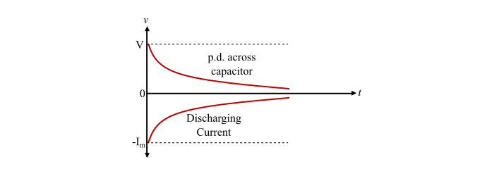
i= -Im e -t/RC….(11)
The graphic representation of the equations for discharging current and discharging voltage is shown below.
Significant Points
The following aspect of a capacitor's operation should be noted:
- A charging current flows when a DC voltage is placed across a capacitor up till the capacitor is fully charged, at which point the current is cut off. In a fraction of a second, the charging process will be completed. Therefore, a completely charged capacitor prevents DC current from flowing.
- Through the external circuit, only electrons are transferred from one plate to the other. The capacitor's plates do not have any current flowing between them.
- The two plates of a capacitor carry an equal and opposing charge when it is charged. Charge on a capacitor therefore refers to charge on both plates.
- The external source provides the energy needed to charge a capacitor.
The Capacitance value of a capacitor, which refers to how much electrical charge it can hold on its plates, is determined by three key elements.
Surface Area: The capacitor's capacitance is determined by the surface area, A, of the two conducting plates that make up the device.
The sort of material that separates the two plates is referred to as the "dielectric," and the higher its permittivity, the higher the capacitance.