Encoder in Digital Electronics
Encoders in Digital Logic
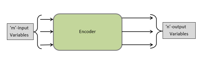
Encoder is a digital circuit in which the performed operation is exactly the opposite of decoders. An encoder consists of a maximum of 2n inputs and produces binary code corresponding to input data as ‘n’ number of outputs. At any instant, among 2n inputs, only one input is HIGH (i.e., logic 1); otherwise circuit has no meaning.
The below-given block diagram shows that the encoder can take any no. of inputs and give many outputs. For each input code, only one output is high. Let say m= no. of inputs and n= no. of outputs, then m ? 2n or n = log2m.
The encoders are used to convert the specific codes into the binary code such as:-
- 8-to-3 line encoder (Octal to Binary encoder)
- 10-to-4 line encoder (Decimal to BCD encoder)
- 16-to-4 line encoder (Hexadecimal to Binary encoder)
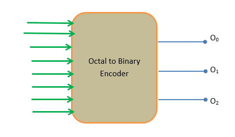
8-to-3 line encoder (Octal to Binary encoder)
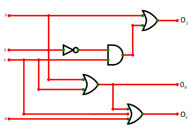
In an 8-to-3 line encoder, there is an input for each of the octal digits. It has eight numbers of inputs, which generates the corresponding binary number and has three outputs. At any instant in time, only one input is high. In case two of the inputs are HIGH simultaneously, the encoder will establish the priority accordingly, so that only one input is encoded at any given time. The encoder can be realized using the OR gates.
Truth table
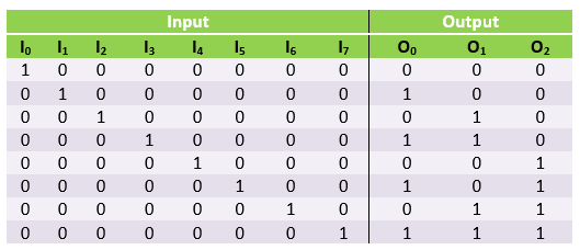
From the above truth table, we obtain that:-
O0 = I1 + I3 + I5 + I7
O1 = I2 + I3 + I6 + I7
O2 = I4 + I5 + I6 + I7
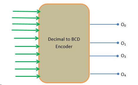
Decimal to BCD Encoder (10-to-4 line Encoder)
The 10-to-4 line encoder takes ten inputs and transmits the information into corresponding BCD code, having four outputs.
Truth table
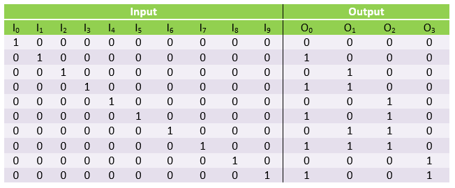
From the above truth table, we obtain that:-
O0 = I1 + I3 + I5 + I7 + I9
O1 = I2 + I3 + I6 + I7
O2 = I4 + I5 + I6 + I7
O3 = I8 + I9
Priority Encoder
The priority encoder is a modified version of a conventional encoder. It eliminates all the limitations that existed with a simple encoder. One of the limitations occurs when more than one input is activated at any instant in time. The priority encoder has the priority function. The priority encoder performs necessary logic to ensure that when two inputs or more inputs are activated simultaneously, the output code will correspond to the "highest-number input."
The truth table for 4-input priority encoder
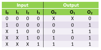
- The 'X' represents the don't care condition, which means the binary value can be equal to 1 or 0.
- The input I3 has the highest priority. So irrespective of the values of other inputs, provided when input I3 is ‘1’. The output for O0 & O1 is ‘1’.
- The input I2 has the second-highest priority. So irrespective of the values of other inputs, provided when input I2 is ‘1’ and input I3 is ‘0’. The output for O0 is ‘1’ & O1 is ‘0’.
- The input I1 corresponds to the output only when higher priority inputs are ‘0’.
- The output O2 is HIGH only when one or more than one inputs are HIGH. If all the inputs are LOW (logic 0), the output O2 is also LOW.
Simplified Boolean expression
O0 = I2 + I3
O1 = I3 + I1 I2’
O2 = I0 + I1 + I2 + I3
Logic diagram for 4-bit priority encoder