4-Bit Ripple Carry Adder in Digital Electronics
What is Ripple carry adder?
- A ripple carry adder is a type of digital circuit that performs binary addition of two n-bit numbers by adding each bit position sequentially, with a carry signal "rippling" from each bit position to the next.
- The basic building block of a ripple carry adder is a full-adder circuit, which takes three inputs: two binary digits to be added and a carry-in bit from the previous bit position, and produces two outputs: the sum of the two binary digits and a carry-out bit that is propagated to the next bit position.
- To construct an n-bit ripple carry adder, n full-adder circuits are connected in a chain, with the carry-out of each stage connected to the carry-in of the next stage. The inputs to the first stage are the least significant bits of the two n-bit numbers to be added, and the output of the last stage is the n-bit sum of the two numbers.
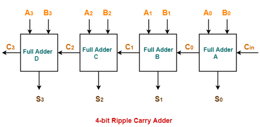
4-Bit Ripple Carry Adder
- A 4-bit ripple carry adder is a specific type of digital circuit that performs the addition of two 4-bit binary numbers by adding each bit position sequentially, with a carry signal "rippling" from each bit position to the next.
- The circuit typically consists of four full-adder circuits connected in a chain, with the carry-out of each stage connected to the carry-in of the next stage. The inputs to the first stage are the least significant bits of the two 4-bit numbers to be added, and the output of the last stage is the 4-bit sum of the two numbers.
- Each full-adder circuit takes three inputs: two binary digits to be added and a carry-in bit from the previous bit position, and produces two outputs: the sum of the two binary digits and a carry-out bit that is propagated to the next bit position.
To understand how the 4-bit ripple carry adder works, let's consider an example of adding the binary numbers 0101 and 0011.
- At the first stage, the least significant bits are added: 1+1 = 0 with a carry-out of 1. The output of the first stage is 0 (the sum of the LSBs) and the carry-out of 1 is propagated to the next stage as the carry-in bit.
- At the second stage, the next least significant bits are added along with the carry-in bit from the previous stage: 0+1+1 = 0 with a carry-out of 1. The output of the second stage is 0 (the sum of the next least significant bits) and the carry-out of 1 is propagated to the next stage as the carry-in bit.
- At the third stage, the next most significant bits are added along with the carry-in bit from the previous stage: 1+0+1 = 0 with a carry-out of 1. The output of the third stage is 0 (the sum of the next most significant bits) and the carry-out of 1 is propagated to the next stage as the carry-in bit.
- At the fourth stage, the most significant bits are added along with the carry-in bit from the previous stage: 0+0+1 = 1 with no carry-out. The output of the fourth stage is 1 (the sum of the most significant bits) and there is no carry-out since this is the most significant bit.
- Therefore, the 4-bit ripple carry adder outputs a sum of 1000 (which is the binary representation of the decimal number 8) and a carry-out of 1 indicating that the addition result overflowed beyond the 4-bit range.
While the 4-bit ripple carry adder is a simple and commonly used circuit for adding two 4-bit binary numbers, it may be too slow for high-speed applications due to the delay in the carry signal rippling through each stage. Other types of adder circuits such as the carry look-ahead adder or the carry save adder may be used to improve performance.
In Mathematics, any two 4-bit binary numbers A3A2A1A0 and B3B2B1B0 are added as shown below-
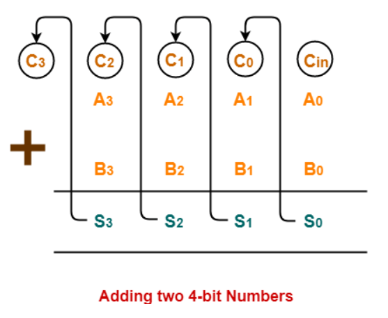
This addition is carried out using the ripple carry adder, as the following logic diagram.
Positive aspects of the ripple carry adder:
The ripple carry adder has a number of positive aspects that make it a popular choice for certain applications. These include:
- Simplicity: The ripple carry adder is a relatively simple with straightforward circuit design, requiring only basic logic gates such as AND, OR, and XOR gates. This simplicity makes it easy to design, simulate, and test, and makes it a popular choice for educational purposes.
- Flexibility: The ripple carry adder can be easily extended to add numbers of any length, by cascading multiple full-adder circuits. This flexibility makes it a versatile choice for a wide range of applications, from small digital circuits to large arithmetic units.
- Design trade-offs: Depending on the specific requirements of an application, the delay and power consumption of the ripple carry adder can be traded off against other design factors such as area, throughput, and error correction capabilities.
- Low hardware overhead: Compared to other adder designs, the ripple carry adder has a relatively low hardware overhead, requiring only a small number of logic gates per full-adder stage. This can make it a cost-effective choice for certain applications.
- Predictable behavior: The ripple carry adder operates in a predictable and deterministic manner, with no unexpected or non-linear behavior. This makes it a reliable and robust choice for many applications.
Negative aspects of the ripple carry adder:
The ripple carry adder has a number of negative aspects that make it less desirable in certain applications. These include:
- Propagation delay: The ripple carry adder requires a certain amount of time for the carry-out signal to propagate from the least significant bit to the most significant bit, which can result in a significant delay in the calculation of the final result.
- Power consumption: Because each full-adder in a ripple carry adder operates sequentially, a large ripple carry adder can require a significant amount of power to operate, especially when adding long binary numbers.
- Area efficiency: The ripple carry adder requires a relatively large number of logic gates to implement, which can make it less area-efficient than other adder designs.
- Limited parallelism: Because each full-adder in a ripple carry adder operates sequentially, it can be difficult to parallelize the addition of multiple binary numbers using this design. This can limit the throughput of the circuit and make it less suitable for certain applications that require high-speed addition of multiple numbers.
- Limited error detection: The ripple carry adder does not provide any error detection or correction capabilities, which can make it more susceptible to errors in the input data or during the addition process.