
Extrude command in AutoCAD
In AutoCAD 3D, the extrude function is useful.
Extrude pushes up the surface, creating a 3D solid from a 2D closed shape or a 3D surface from an object with open ends.
If you have any closed 2D drawings, you may use the Extrude command in AutoCAD 3D to convert them to 3D.
Creates a 3D solid or a 3D surface from an item with open ends or an object that encloses an area.

Objects can be extruded orthogonally from the source object's plane, in a certain direction, or along a predetermined route. A taper angle can also be specified.
When a solid or surface is generated, the DELOBJ system variable determines whether the source objects or specified path are automatically destroyed or whether you are requested.
Objects to Extrude
The objects to extrude are specified.

Note: While selecting face and edge subobjects, hold down the Ctrl key.
The extruded object's mode determines whether it is a solid or a surface.
Depending on the SURFACEMODELINGMODE system variable, surfaces are extruded as NURBS or procedural surfaces.
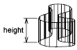
Maximum extrusion height
Select items are extruded along the positive or negative Z axis. The orientation is determined by the current UCS at the time the item was produced, or by the original UCS of the most recently generated object (for multiple options).
Direction
With two given points, specifies the length and direction of the extrusion. (The direction must be perpendicular to the plane of the extrusion's sweep curve.)
Path
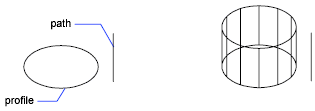
Extrusion path specified depending on a chosen item. The route is relocated to the profile's centroid. The selected object's profile is then extruded along the chosen route to generate solids or surfaces.
Note: While selecting face and edge subobjects, hold down the Ctrl key.
The route should not be in the same plane as the item, and areas of significant curvature should be avoided.
Extrusion begins at the object's plane and retains its orientation in relation to the route.
If the route includes non-tangent segments, the software extrudes the item along each one before mitering the joint along the plane bisecting the angle created by the segments. The item should lie on the miter plane if the route is closed. This permits the solid's start and end parts to line up. The item is rotated until it is on the miter plane if it is not already there.
Extrude objects with many loops so that all of the loops appear on the same plane at the extruded solid's end section.
Angle of taper
The taper angler for the extrusion is specified.
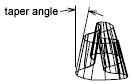
From the base object, positive angles taper in. Negative angles gradually diminish. Extruding a 2D object perpendicular to its 2D plane is the default angle of 0. All of the chosen objects and loops have the same taper value.
When you provide a significant taper angle or a lengthy extrusion height, the item or parts of the object may taper to a point before reaching the extrusion height.
A region's individual loops are always extruded to the same height.
When an arc is part of a tapered extrusion, the arc's radius decreases but its angle remains constant.
- The taper angles. The taper should be between -90 and +90 degrees.
- Choose two points. The taper angle is defined based on two points. The distance between the two stated positions is the taper angle.
To set and preview the taper angle, drag the pointer horizontally. You may also change and preview the height of the extrusion by dragging the pointer. The dynamic input origin should be on the extruded form, on the point's projection onto the shape.
The position of the taper grip on the top face of the extrusion corresponds to the dynamic input origin when you choose the extruded item.
Expression
To specify the extrusion height, use a formula or equation.
Extrude in AutoCAD
1) After converting model space to '3D modelling,' we must create a 2D extruded object.
2) The Extrude command can only be used on polyline closed surfaces like squares, rectangles, circles, ellipses, and so on. We can extrude it as a single line surface like paper if it is not closed or polyline.
3) If you require a rectangle to be extruded, draw one. Draw a circle if you require a cylinder.
4) Press the Enter key after selecting the Extrude command from the 'Modeling' panel or typing 'EXT' in the command box.
5) It will then prompt you to 'Select object to extrude.' To extrude, choose a 2D object.
Extrusions in AutoCAD: Different Types
1) AutoCAD Solid Extrude
2) AutoCAD Surface Extrude
3) Extrude Direction
4) Extrude Path
5) Angle of Taper
1) AutoCAD Solid Extrude
Too solid; we must right-click and select Enter from there after picking the item surface.
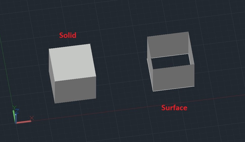
2) AutoCAD Surface Extrude
1) After choosing the surface of the object, right-click and pick 'Mode' from there, then 'Surface' from there to extrude only the surface of the line or polyline.
2) If the item is not closed, the surface will extrude.
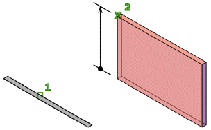
3) It will then ask you to "specify the height of extrusion." Provide the appropriate extrusion height. We may also set the height by selecting any reference line point, as illustrated.
4) The '2D wireframe' will reveal it. We may switch to 'Realistic' from the '2D wireframe' in the workspace's upper left corner, as illustrated.