
Mesh Command in AutoCAD
It creates a 3D mesh basic object, such as a wedge, torus, box, cone, cylinder, pyramid, or other shape.

Find
Mesh primitives, or the fundamental mesh shapes, are comparable to the 3D solid primitive forms.
By smoothing, creasing, refining, and separating faces, you may reshape mesh objects. Additionally, you may move vertices, faces, and edges to modify the overall shape.
Note: By default, smoothness is not applied while creating new mesh primitives. Enter MESH at the Command prompt to alter the smoothness from the default setting. Prior to specifying the kind of mesh primitive, you wish to construct, select the Settings option.
The following questions are shown.
Box makes a box with a 3D mesh.
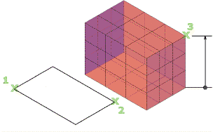
Indicate how long each side should be.
- Corner / First corner is the mesh box's corner is set.
- Center establishes the mesh box's center.
- Cube sets the box's edges to have identical lengths.
- Length sets the length of the mesh box along the X axis.
- Width is the mesh box's width along the Y axis is determined by width.
- Height fixes the height of the mesh box along the Z axis.
- 2Point (height) is based on the separation of two locations to determine the height.
Cone creates a 3D mesh with a base that is symmetrically circular or elliptical and tapers to a point or a planar face.
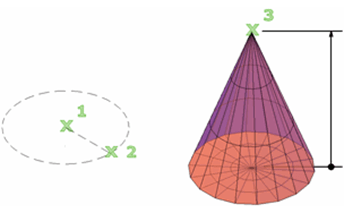
Give the height and diameter.
- central axis of the base establishes the mesh cone's base's central point.
- 3P (three points) specifies three points to determine the mesh cone's position, dimensions, and plane. The third point determines the cone base's dimensions and planar rotation.
- 2P (diameter) based on two locations, establishes the mesh cone's base diameter.
- Ttr (tangent, tangent, radius) defines the mesh cone's base, which has a certain radius and is tangent to two points on the objects:
- Set initial tangent point at the target. establishes a point on an object that will act as the initial tangent.
- Focus on the target for the second tangent. establishes a point on an object that will act as the second tangent point.
- Radius of a circle. establishes the mesh cone base's radius. The nearest tangent points are utilized when the given criterion might provide more than one outcome.
- Elliptical specifies that the mesh cone's base be elliptical.
- Beginning of the first axis. sets the endpoints of the remaining axes after setting the start point for the mesh cone base's first axis.
- Center. Describes how to start at the base's center point and build an elliptical mesh cone base. The second step is to set the second axis' endpoint and the distance from the first axis' radius.
- Base radius establishes the mesh cone base's radius.
- Diameter determines the cone's base's diameter.
- Height adjusting the mesh cone's height along an axis perpendicular to the base's plane.
- 2Point (height) by providing the separation between two locations, the height of the mesh cone is determined.
- Point of an axis determines the location of the cone's top point or the centre of a cone frustum's top face. Anywhere in 3D space can have an axis endpoint with any orientation.
- upper radius creates a cone frustum by specifying the cone's top radius.
Cylinder creates a cylindrical 3D mesh.
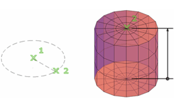
Indicate the base and height measurements.
- Central axis of the base establishes the mesh cylinder base's central point.
- 3P (three points) (three points): By selecting three points, the mesh cylinder's position, size, and plane are changed. The mesh cylinder base's size and planar rotation are determined by the third point.
- 2P (diameter): Two locations are specified in 2P (diameter) for the mesh cylinder base's diameter.
- 2Point (height): The mesh cylinder's height is determined by the 2Point (height) specification of the separation between two points.
- Ttr (tangent, tangent, radius): The mesh cylinder's base, which has a certain radius and is tangent to two objects, is defined by the formula ttr (tangent, tangent, radius).
- Base diameter establishes the mesh cylinder base's radius.
- Diameter determines the cylinder's base's diameter.
- Height sets the mesh cylinder's height along an axis perpendicular to the base's plane.
- Point of an axis determines where the cylinder's upper face will be. Anywhere in 3D space can have an axis endpoint with any orientation.
- Elliptical specifies an elliptical mesh cylinder foundation.
- Beginning of the first axis. It establishes the beginning and end of the mesh cone base's first axis. then establishes height (second axis endpoint).
- Center. Describes how to build an elliptical mesh cone base, starting at the base's center and specifying the radius and height.
Pyramid makes a pyramid out of 3D mesh.
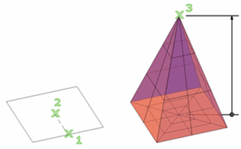
Give the height and diameter.
- Central axis of the base establishes the mesh pyramid base's central point.
- Edge establishes the length of the mesh pyramid base's one edge, as specified by the two locations you provide.
- A side determines the mesh pyramid's side count. Enter a positive number between 3 and 32.
- Base diameter establishes the mesh pyramid base's radius.
- Inscribe specifies that the mesh pyramid's base is drawn inside or inscribed within the base radius.
- Height Set the mesh pyramid's height along an axis that is perpendicular to the base plane.
- 2Point (height) specifies the distance between two locations, defining the height of the mesh cylinder.
- Point of an axis establishes the position of the pyramid's highest point or the centre of a pyramid frustum's top face. Anywhere in 3D space can have an axis endpoint with any orientation?
- Upper Radius creates a pyramid frustum by specifying the mesh pyramid's top radius.
- Circumscribed specifies that the pyramid's base is drawn around or circumscribed by the base radius.
Sphere is a sphere made with a 3D mesh.
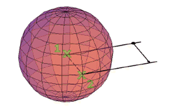
Define the sphere's size (diameter or radius).
- The center establishes the sphere's center.
- Radius. Based on a given radius, generates a mesh sphere.
- Diameter. Creates a mesh sphere with the specified diameter.
- 3P (three points) specifies three points that together determine the mesh sphere's position, size, and plane.
- 2P (diameter): By selecting two locations, the mesh sphere's diameter may be changed.
- Ttr (tangent, tangent, radius) The following defines a mesh sphere with a certain radius that is perpendicular to two locations on objects: When more than one result may be produced by the given criteria, the nearest tangent points are utilized.
Wedge is a 3D mesh wedge is produced.
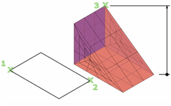
Indicate the base's height, breadth, and length.
- Initial corner establishes the mesh wedge base's initial corner.
- Other side establishes the X, Y-plane opposite corner of the mesh wedge base.
- Center establishes the mesh wedge base's central point.
- Cube Ensures that the mesh wedge base's edges are all set to the same length.
- Length determines the mesh wedge base's length along the X axis.
- Width determines the mesh box's width along the Y axis.
- Height determines the mesh wedge's height. To draw the height along the positive Z axis of the current UCS, provide a positive number. To draw the height along the negative Z axis, enter a negative number.
- 2Point (height) specifies the distance between two locations, defining the height of the mesh wedge.
Torus makes a rudimentary torus 3D mesh.
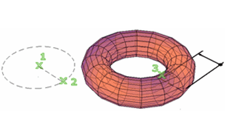
Give two values: the tube's diameter and the separation between its and the torus's centres.
- Center point establishes the mesh torus's center point.
- 3P (three points) (three points) specifies three places along the path that the tube travels through to determine the position, diameter, and rotation of the mesh torus.
- 2P (torus diameter) specifies two places to set the mesh torus's diameter. From the torus's center point to the tube's center point, the diameter is computed.
- Ttr (tangent, tangent, radius) defines the radius of a mesh torus that is perpendicular to two objects. Projections into the current UCS are made at the given tangent points. The nearest tangent points are utilised when the given criterion might provide more than one outcome.
- Radius (torus) establishes the mesh torus's radius, which is determined by measuring the distance between the tube's and the torus's centers.
- Diameter (torus) establishes the mesh torus's diameter, which is determined by measuring the torus's diameter between its center and the tube's center.
- tube diameter the radius of the profile that is swept around the mesh torus route is set.
- 2Point (tube radius) depending on the separation between two spots, determines the radius of the tube's profile.
- Tube diameter sets the mesh torus tube's profile's diameter.
Settings changes the new mesh object's smoothness and tessellation parameters.
Smoothness level establishes the mesh's initial level of roundness or smoothness. To obliterate smoothness, enter 0. Enter a positive number up to 4 for smoothness levels to be raised. For the duration of the current drawing session, the value is kept.The value of SMOOTHMESHMAXLEV sets a limit on this smoothness parameter.