×

Join Command in AutoCAD

In AutoCAD, the Join command is used to join the objects end to end to form a single entity. Depending on the requirements, the objects might be curved or straight.

It creates a single 2D or 3D object by combining a succession of linear and curved objects.

To link any item, follow these steps.

Let's have a look at how to link any line or object.

The steps are as follows:

  1. Select the Join command from the Modify interface's ribbon panel.

   Or

   On the command line, type J or join and hit Enter.

  • To link numerous items, we must first choose them. The selected items are all linked at the same time.
  • Enter

The chosen objects will be fused together to form a single unbreakable object.

Consider the following scenario.

Example:

We shall discuss this in this section.
Join Command in AutoCAD

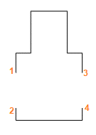
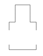
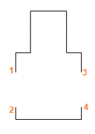
We are required to join the segments numbered 1, 2, 3, and 4. These segments are shown below:
Join Command in AutoCAD

To join the segments marked above, follow these steps:

  1. On the command line or at the command prompt, type J or join and hit Enter.
  2. Segments 1 and 2 should be chosen.
  3. Press the Enter key.
  4. 3 and 4 segments should be chosen.
  5. Enter.
Join Command in AutoCAD

As illustrated in the figure below, the portions will be connected together:

The following are the types of objects that can be joined with the JOIN command:

1. Lines

Only the source line can be linked to the line objects.

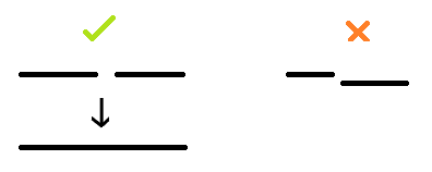
There is no restriction on the amount of space between the points on the line.

The lines' terminals should be parallel to the straight line. The following graphic explains it:
Join Command in AutoCAD

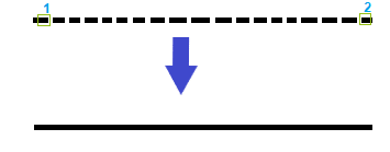
We can also make a single line out of the series of lines.

The initial and last segments of the series must be specified here.

The following graphic depicts the above procedure:
Join Command in AutoCAD

2.Arcs

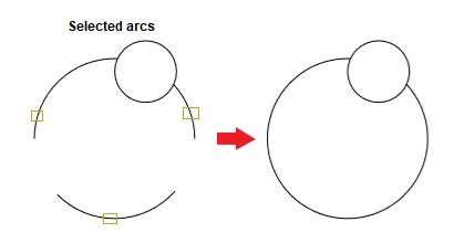
Only the source arc can be linked to the arcs. The arc's radius and canter point must be the same. There may be gaps between the arc's segments. Consider the following scenario.

The image is as follows:
Join Command in AutoCAD

3.Polyline

To the source arc, lines, arcs, and polylines can be linked.

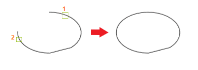
Elliptical Arcs are a type of elliptical arc.

Only the chosen elliptical arc can be linked to the elliptical arcs. The elliptical arc's major and minor axes must be the same. The arc should be parallel to the ground. Space between the elliptical arcs is possible.
Join Command in AutoCAD

4.Polylines in three dimensions

The provided 3D Polyline can be linked to the linear or curved object. The objects should be contiguous and noncoplanar.

5.Helixes

The specified helix can be attached to the linear or curved object. The objects should be contiguous and noncoplanar.

6.Splines

The chosen spline can be linked to the linear or curved object. The objects should be contiguous and noncoplanar.

  • Multiple items can be joined at the same time.
  • Without specifying a source object, joins multiple items. The following are the rules and the resulting object types:
  • Collinear lines are joined to form a line object. There may be gaps between the endpoints of the lines.
  • Coplanar arcs with the same center point and radius are joined to form an arc or circle object. There may be gaps between the endpoints of the arcs. The lengthening happens in a clockwise manner. If the linked arcs create a complete circle, the result is a circle object.
  • Joining splines, elliptical arcs, or helixes together, or to other objects, produces a spline object. Non coplanar objects are possible.
  • Joining coplanar lines, arcs, polylines, or 3D polylines yields a polyline object.
  • Joining noncoplanar items that aren't curved produces a 3D polyline.

In AutoCAD, how do you attach lines to polylines?

According to the position of the line and polyline, there are two conditions.

Examine your situation and take the following steps:

In AutoCAD, condition 1 is to join lines to polylines.

1) Both the line and the polyline are at a 0 degree angle (Straight).

2) Select Modify panel from the drop-down option. Then choose the "Join" command. Alternatively, put "JOIN" in the command bar and hit Enter.

3) Then, one by one, right-click each line and polyline.

4) Both lines will come together.


Related Topics

Rectangle command in AutoCAD

The rectangle command is used to create rectangles in our drawing. We can create rectangles randomly by specifying the points and also by specifying the values of length and width. METHOD 1:-...

3 minutes read.

AutoCAD Tutorial

In 1982, a group of programmers led by John Walker constructed the initial version of AutoCAD, which Michael Riddle, another member of the team, had previously designed. The popularity of...

5 minutes read.

Array Command in AutoCAD

AutoCAD's Array Command From the command line, creates duplicates of anything in a pattern. Creates nonassociative, 2D rectangular or polar arrays using historical command line behavior. The copies may take a long...

3 minutes read.

Mesh Command in AutoCAD

It creates a 3D mesh basic object, such as a wedge, torus, box, cone, cylinder, pyramid, or other shape. Find Mesh primitives, or the fundamental mesh shapes, are comparable to the 3D...

6 minutes read.

Command list of AutoCAD

Fundamental AutoCAD Commands Here is a summary of some of the most fundamental AutoCAD commands that every user should be familiar with. These Draw and Modify instructions make up part of...

12 minutes read.

Create Block in AutoCAD

Blocks In AutoCAD, the term "blocks" refers to repetitive things that you insert in your designs. Symbols is another name for them. In AutoCAD, the words "Block Library" and "Symbol Library"...

3 minutes read.

Donut Command in AutoCAD

A donut is formed by joining two arc polylines end to end to form a circular shape. The selected interior and outer diameters define the width of the polylines. When...

4 minutes read.

Attedit command in AutoCAD

At the Command prompt, modify a block's attribute data. You may filter the properties that need to be changed based on the attribute tag, the current value, or the selected...

4 minutes read.

Annotation command in AutoCAD

When the project's author is not there, AutoCAD annotation gives the project all of its meaning and its purpose to the eyes of someone viewing it. Additionally, annotations can assist...

3 minutes read.

Overkill Command in AutoCAD

Getting rid of overlapping objects in AutoCAD In the command bar, enter the word OVERKILL.Choose every item you wish to be eliminated of duplicates. To accept the drawing chosen, press enter. Review...

4 minutes read.

Join Command in AutoCAD

In AutoCAD, the Join command is used to join the objects end to end to form a single entity. Depending on the requirements, the objects might be curved or straight. It...

3 minutes read.

Hatch command in AutoCAD

In AutoCAD, the Hatch command is used to fill patterns inside an enclosed region. Hatched, gradient, and solid fill designs are available. A gradient pattern is a seamless transition between two...

5 minutes read.

AutoCAD Software

Computer-aided design software allows you to produce 2-D and 3-D drawings and models instead of using traditional pencil-and-paper drafting to develop designs that can be readily changed. History Autodesk is the company...

5 minutes read.

Subtract command in AutoCAD

In AutoCAD, use the subtract command. Use the subtract command in AutoCAD. By subtracting one set of existing 3D solids from a second, overlapping set, SUBTRACT may be used to...

3 minutes read.

Stretch command in AutoCAD

How to use Stretch command in AutoCAD 1) This command in AutoCAD is excellent and helpful. Use the Stretch command to quickly move or alter any items, such as a door...

4 minutes read.

Explode command in AutoCAD

When you need to deconstruct a component into its sub-components, AutoCAD's EXPLODE tool comes in helpful. This allows you to alter each of the sub-components independently. One of the first examples...

4 minutes read.

LINETYPE Command in AutoCAD

linetypes are loaded, set, and modified.    Find It displays the Linetype Manager. Options are shown when you use -LINETYPE at the Command prompt. linetypes are loaded, set, and modified at the command prompt. The following...

3 minutes read.

Copy Command in AutoCAD

Using Two Points to Copy an Object Select the Home tab > Modify panel > Copy option.Press Enter after selecting the items to copy.Set a starting point for the copy.Make a...

3 minutes read.

Sweep Command in AutoCAD

We'll utilize the SWEEP command here, which, like the EXTRUDE function we used when we produced our first figure in AutoCAD, helps us get cylinders out of circles and can...

4 minutes read.

Trim command in AutoCAD

TRIM (Command) You have two options for trimming objects: Quick mode and Standard mode. Quick Mode is the fastest mode. To trim items, individually select them, push and drag to start a...

6 minutes read.