
Revolve Command in AutoCAD
The Revolve command in AutoCAD 3D is employed to form a 3D solid or surface by sweeping the thing through its axis at a predefined angle.
The paths and objects that can be revolved are:
- Planar
- Non-planar
- Open
- Closed
- Solid
- Surfaces
- Circles
- Arcs
- Revolve path and profile curves can be:
- Open or closed
- Planar or non-planar
- Solid and surface edges
A single object (to extrude multiple lines, convert them to one object with the JOIN command)
A single region (to extrude multiple regions, first convert them to one object with the UNION command)
The positive direction of rotation is decided by the right-hand thumb rule
The following prompts are displayed.
Objects to Revolve
Specifies the objects to be revolved about an axis.
- Mode
Controls whether the revolve action creates a solid or a surface. Surfaces are extended as either NURBS surfaces or procedural surfaces, betting on the SURFACEMODELINGMODE system variable.
- Axis Start Point
Specifies the primary point of the axis of revolution. The positive axis direction is from the primary to the second point.
- Axis Endpoint
Sets the endpoint for the axis of revolution.
- Start Angle
Specifies an offset for the revolution from the plane of the article being revolved.
Drag your cursor to specify and preview the beginning angle of the article.
- Angle of Revolution
Specifies how far the chosen object revolves about the axis.
A positive angle revolves the objects during a counterclockwise direction. A negative angle revolves the objects during a clockwise direction. you'll also drag the cursor to specify and preview the angle of revolution.
- Reverse
Changes the direction of the revolve; kind of like entering a - (minus) angle value. The revolved object on the proper shows a spline revolved at the identical angle because the object on the left, but using the reverse option.
Expression
Enter a formula or equation to specify the revolve angle.
- We can rotate the article with relation to X-axis, Y-axis, and Z-axis.
How to Use Revolve Command in AutoCAD?
1: At the highest of the working screen, we've a ribbon which has many various sorts of tabs like Home tab, View tab, Insert tab, Annotation tab, and a few others; below this, we've a working window within which we are able to see our current working, below this working window we've got some navigation tabs for creating our drawing work easy during this software.
2: Now, we've to alter the workspace screen of this software to 3d basic for 3d commands for revolve command because revolve is 3d command. So for changing the workspace screen, attend the workspace switcher option, which is on the correct side of the underside end of the working screen. Now click on the workspace switcher option and choose 3d basic option from the list by click on that.
3: Now, allow us to make a circle within the front view of this software by circle command.
4: Now, allow us to change our view from this View control option. So click on this feature and choose SE Isometric options from the list.
5: Now attend Create tab of the house menu of the 3d basic workspace screen and click on on this icon which revolves command for having revolved command active.
6: you'll use a shortcut key for revolve command, which is REV, then press the enter button of the keyboard for having revolved command active.
7: Now, it'll ask you to pick the article. So click on the boundary of this circle for choosing it.
8: Then it'll ask you to allow the axis within which you would like to revolve your object. I will be able to give the x-axis then press the enter button on the keyboard.
9: And your object will revolve like this.
10: Now, it'll ask you to enter the worth of revelation at which you wish to revolve your object. I’ll enter 360 degrees as a revolution angle. you'll be able to take it per you.
11: And your object will revolve like this. this is often a 2d wireframe view of this 3d
object.
12: you'll change it into a shaded view from this software’s view style option, which is at the highest left corner of this working screen.
13: And your object will seem like this in shaded form.
14: you can't revolve your 2d shape within the same plane of the article. for instance, I drew this circle within the z plane, and once I want to revolve it within the z-axis by specifying the z-axis of revolution in revolving command, then press the enter button of the keyboard.
16: Now, allow us to discuss other options of this command for our better understanding of this command. Again take revolve command. Then click on the Mode option of the parameters box of this command.
17: Now, there are two options within the mode option of this command that's Solid and Surface. allow us to understand both one by one. So I will be able to click on the solid option first.
18: Now, it'll ask you to relinquish the axis you would like to revolve. i will be able to give the Y axis then press the enter button of the keyboard.
19: And it'll revolve like this. Now enter the angle of revolution. I’ll provides it a 180 degree.
20: Now, once you orbit this 3d shape, you'll see it's a solid shape. So with the solid option, you'll make a solid 3d shape.
21: Now again, take revolve command, follow the identical steps, then choose the Surface option within the mode option.
22: Again, give the axis of revolution, then press enter button of the keyboard then the angle of revolution.
23: Now, once you orbit this shape, you'll see this can be the hollow shape. So with the surface option, you'll be able to make only the surface of any object.
24: Now, allow us to again take revolve command can select this circle, then press the enter button of the keyboard; you'll be able to see two options within the parameters section of this command, so choose the item option from this list.
25: Now, it'll ask step 27: you'll give the worth of the angle of revolution in line with you.ou to pick out the article around which you would like to revolve it. I will be able to click on this line.
26: And your object will revolve around this line like this.
27.You can give the value of the angle of revolution according to you.
28: you'll make beautiful objects with this revolve command. I draw a 2d shape like this. confirm the form which you wish to revolve should connect in one object.
29: Now, change the view to the SW Isometric view.
30: And again, take revolve command and revolve this shape around this line.
31: And your shape will revolve like this
32: So, during this way, you'll be able to make an object with this command.
We are required to use polyline to form a base for revolve command.
We can either join the lines or segments before revolving. revolve-command-in-autocad
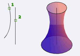
Let's understand with few examples.
Example 1:
To revolve with reference to X, Y, or Z-axis.
Consider the below 2D object:
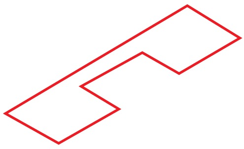
Make sure to activate the ortho mode.
The above object is drawn in SE Isometric Mode.
The above object was first joined.
Place the UCS icon on the item.
The steps are listed below:
STEP 1. Create the above figure.
STEP 2. Select Revolve icon from the ribbon panel, as shown below:
Or
Type REV or revolve on the command or electronic communication and press Enter.
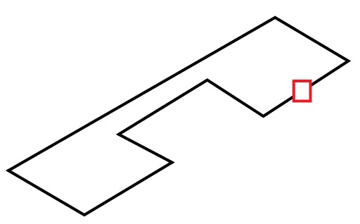
STEP 3. Select the item to revolve with a little square cursor, as shown below:
STEP 4. Press Enter.
STEP 5. Specify the X, Y, or Z axis.
If X-axis is selected:
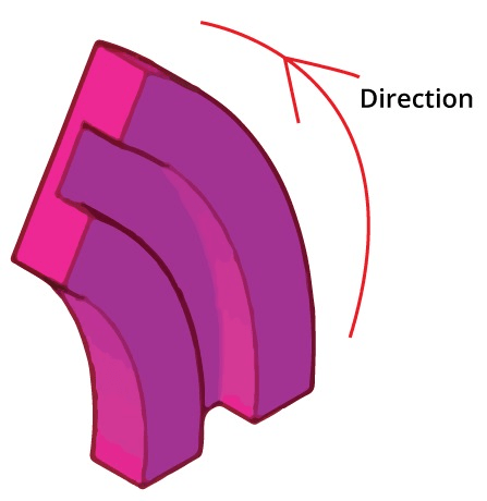
If Z-axis is selected:
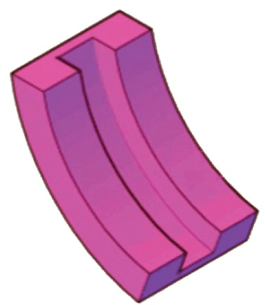
STEP 6. Press Enter.
STEP 7. Specify angle of revolution.
STEP 8. Press Enter.
To revolve in line with the axis line, follow the below steps:
STEP 1. Type REV or revolve on the command or electronic communication and press Enter.
STEP 2. Select the thing to revolve with a tiny low square cursor, as shown below:
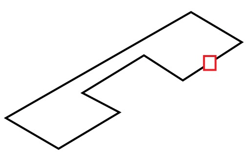
STEP 3. Press Enter.
STEP 4. Specify axis start point of the thing to be revolved.
STEP 5. Specify axis endpoint.
STEP 6. Specify angle of revolution.
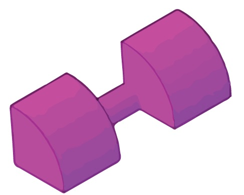
If the desired angle = 30, the item will seem like the below image:
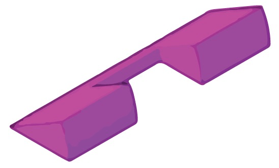
If the required angle = 360, the item will seem like the below image:
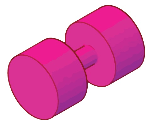
If the required angle = 360, the article will appear as if the below image:
STEP 7. Press Enter.
To revolve as a surface, follow the below steps:
STEP 1. Type REV or revolve on the program line or prompt and press Enter.
STEP 2. Type M or mode on the command < press Enter.
STEP 3. Type Surface or S on the command < press Enter.
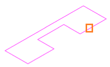
STEP 4. Select the item to revolve with little square cursor, as shown below:
STEP 5. Press Enter.
STEP 6. Specify axis start point of the item to be revolved.
STEP 7. Specify axis endpoint.
STEP 8. Specify angle of revolution.
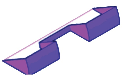
If the desired angle = 30, the article will look like:
STEP 9. Press Enter.
We can easily notice the difference between the surface and solid.
Example 2:
The base is formed in 2D TOP view control.
Consider the below object:
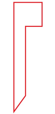
Change TOP view control to SE Isometric, as shown below:
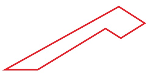
Apply Revolve command and specify the beginning and end axis. Specify angle = 360.
The object will appear as:
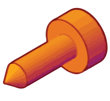
Other view of the thing is shown below:
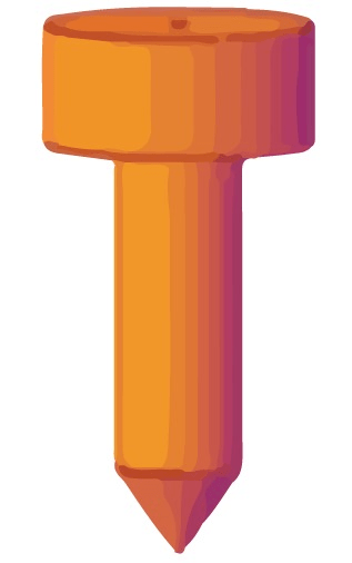
You can modify the angle value in step with the wants.
Example 3:
The base is formed in 2D TOP view control.
Consider the below object:
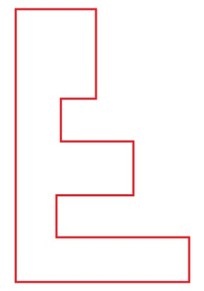
Change TOP view control to SE Isometric, as shown below:
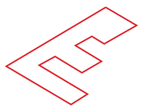
Apply Revolve command and specify the beginning and end axis. Specify angle = 360.
The object will appear as:
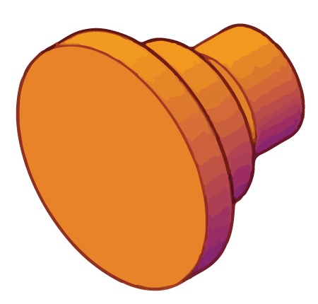
Other view of the article is shown below:
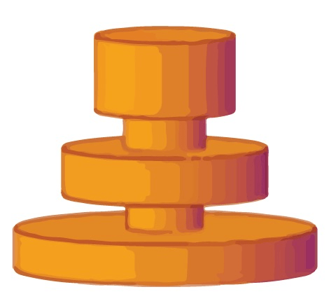
You can modify the angle value in step with the necessities.
Similarly, we are able to create many objects.
The views of the article also can be adjusted by the Orbit command.
The system variable named as SURFACEMODELINGMODE are often wont to extend the surfaces as procedural or NURBS surfaces.