
Stretch command in AutoCAD
How to use Stretch command in AutoCAD
1) This command in AutoCAD is excellent and helpful. Use the Stretch command to quickly move or alter any items, such as a door or window, without exerting any effort.
2) Some objects can't be extended, including circles, ellipses, and CAD blocks.
3) AutoCAD stretches don't function with everything here. The selection of an item for stretch is the key component of the stretch command.
4) To choose your things correctly, use the "Window" (left to right) or "Crossing Window" (right to left) selecting techniques
5) This tool is added to the home tab's customized panel.
6) You may also enter "S" in the command bar to quickly access the AutoCAD stretch function.
7) hit the Enter key. It will then run the Stretch command.
Use the AutoCAD stretch command by following these steps.
1) In AutoCAD, choose this command from the edit panel under the home tab. instead, enter the letter S into the command bar.
2) This command will prompt you to "choose item" once you choose it. Choose the object using the "left to right" or "right to left" selection techniques.
3) The "Right to Left" selection and this command work best together.
4) Right-click.
5) Decide where you want to start extending the item from. Drag the item while maintaining left click. then let it go. Or provide any dimension for the object's stretch.
6) The item will stretch.
7) AutoCAD's stretch hatch, stretch block, and other features don't function.
8) The approach described above only works with the AutoCAD stretch line, which extends numerous lines.
AutoCAD's Stretch function is used to extend the area of an object that is partially encircled by a polygonal or window selection.
It is impossible to extend the things that have been individually chosen or fully encircled by a window selection. Ellipses, blocks, and circles are examples of things that are rather moved.
Objects that are intersected by a selection window or polygon are stretched.
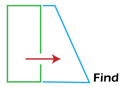
Objects partially encircled by a crossing window are stretched. Objects that are totally encompassed or individually selected within the crossing window are moved rather than stretched. Circles, ellipses, and blocks are examples of things that cannot be extended.
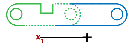
The following prompts will appear.
Objects to be chosen
This parameter specifies the part of the object you wish to stretch. Use the crossing object selection technique or the cpolygon option. When you've finished making your decision, press Enter.
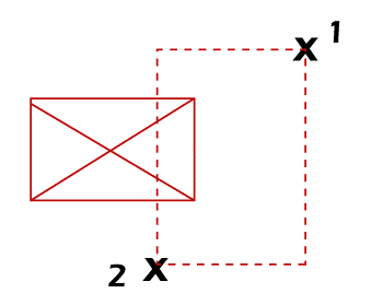
STRETCH just moves the vertices and endpoints inside the crossing selection, leaving the rest untouched. STRETCH has no impact on 3D solids, polyline width, tangent, or curve-fitting data.
Base Line establishes the point at which the stretch offset will be calculated. This base point might be located outside of the extended area.
The second point is this:
Sets a second point that determines the stretch's length and direction. This point's distance from the base point determines how far and in which direction the selected pieces of the object will be stretched.
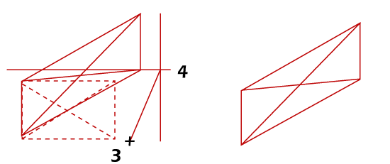
As a displacement, use the first point.
The stretch distance and direction will be determined by the distance and direction of the base point you indicated in the drawing's 0,0,0 parameters.
Displacement
The stretch's relative distance and direction are specified.
Enter distances in the X, Y, Z format to establish a displacement depending on the relative distance from the present location. To stretch the selection 5 units along the X axis and 4 units along the Y axis from the beginning location, type 5,4,0, for instance. To set the displacement based on the distance and direction from the 0,0,0 coordinates, click a point in the drawing area. To move the selection 1 unit along the X axis and 2 units along the Y axis from its current location, click a point at 1,2,0, for instance.
Example 1
Look at the photo below:
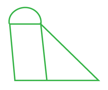
Stretch AutoCAD
Following is a list of the stages for such an example:
- From the ribbon panel, choose the Stretch symbol as seen below:
Stretch AutoCAD
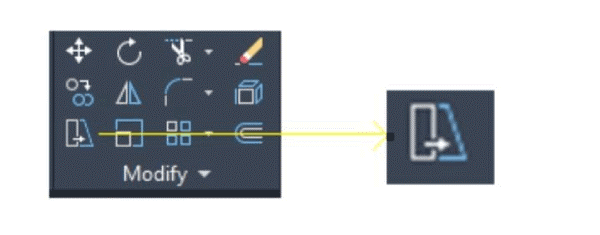
On the command line or command prompt, enter S or stretch.
- Choose the item. With the use of box selection, we have chosen the item, as shown below:
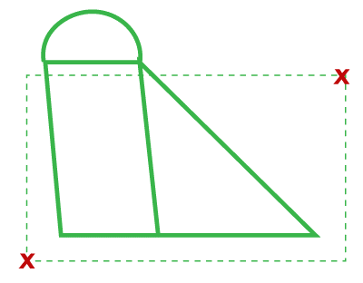
- Enter the key.
- Indicate the displacement value or base point.
The displacement value may also be specified in coordinates (X, Y, Z format).
Here, as indicated below, we have supplied the base point:
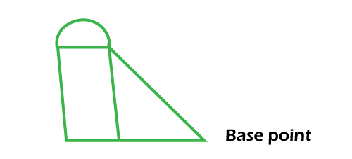
- Indicate the second point or the displacement amount. If the second point is clarified as follows:
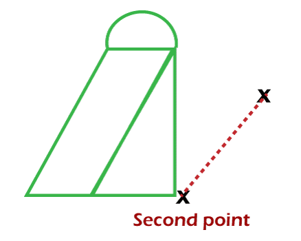
The base point was the object's initial base point, while the second point is the object's extended base point.
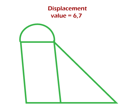
Set the displacement value to 6 and 7. The item will now resemble the picture below:
Example 2
Look at the photo below:

Following is a list of the stages for such an example:
- From the ribbon panel, choose the Stretch icon.
or
On the command line or command prompt, enter S or stretch.
- Choose the item. Here, as indicated below, we have chosen a portion:
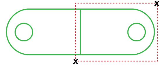
- Enter the key.
- Indicate the displacement value or base point.
Here, as indicated below, we have supplied the base point:
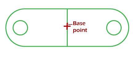
- Indicate the second point or the displacement amount.
The second point has been clarified as follows:
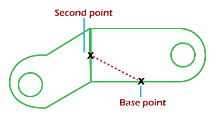
The base point was the object's initial base point, while the second point is the object's extended base point.
By defining the displacement value in accordance with the needs, we may also stretch it.