
×

Isoplane command in AutoCAD

It's possible that you'll need to create isometric drawings if you operate in the plant business. If you use AutoCAD, you might wish it was simple. You may.

By merely changing the drawing's orientation, it becomes a 2D drawing rather than a 3D one. You may achieve it by using Snap and switching to isometric mode.

Although isometric drawings are created using 2D geometry, they give the impression of being in three dimensions. By tilting the viewing angle to 30 degrees for each of the design's sides in the 2D plane, an isometric drawing may be created in AutoCAD.
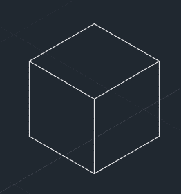
Isoplane command in AutoCAD

I'll demonstrate how to create an isometric drawing in AutoCAD in this tutorial. I'll utilize the geometry in the above image to demonstrate this characteristic.

You may view a video I made to explain this technique here. If you would rather read an article than watch a video, scroll down to do so.

In AutoCAD 2014 and earlier versions, isometric drawing:

At first, you need to modify your snap settings to isometric. On the command line, type DS and hit Enter.

A window with draught settings will appear from this one. Make sure the Isometric snap radio button is checked under the snap and grid tab. To close the drafting settings window, click OK.
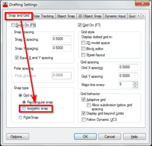
Isoplane command in AutoCAD

Now check to see if ortho mode is on in the status bar; if not, hit F8 to enable it.

Isoplane command in AutoCAD

By using the F5 key, you may now choose the isometric plane for your design. There are three isoplanes to choose from: the top, right, and left isoplanes.

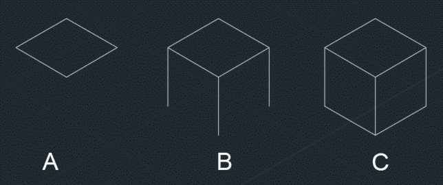
To start drawing a line, click anywhere in the drawing area after selecting the line command and pressing the F5 key to enable Isoplane Top. To create a closed square like the one in figure A below, specify a direction and write 5, then hit enter. Repeat this step while adjusting the direction of the line.
Isoplane command in AutoCAD

To move the isoplane to the right or left, press F5 once again. Restart the line command and draw lines, as shown in figure B above, starting at the three corners of the square that are 5 units long and pointing downward.

In AutoCAD 2015 and later versions, isometric drawing:

This procedure of producing an isometric design has been substantially simplified with AutoCAD 2015 and subsequent versions. Using the ISODRAFT option in the status bar, you may begin isometric sketching immediately.

Isoplane command in AutoCAD

Select the plane on which you wish to make your design by clicking the ISODRAFT symbol in the status bar as seen in the above image and pressing the F5 key. The remaining steps are the same as those described earlier.

ISODRAFT Command

identifies the current 2D isometric drafting plane and enables or disables isometric drafting options.

The ISOPLANE command has been replaced by the ISODRAFT command. The main benefit of ISODRAFT is that every linked parameter is adjusted automatically when it is switched on or off.

When illustrating 2D isometric representations of 3D objects, ISODRAFT automatically regulates the following parameters and modes:

  • orthodox guidelines
  • Snap positioning
  • Grid dimensions and appearance (dotted)
  • Angles of polar tracking
  • Circular isometric orientation

The suitable axis pair from 30, 90, and 150 degrees is used in ortho mode.

The direction of isometric circles made with the ELLIPSE command's Isocircle option depends on the current isometric plane as well.

Isoplane command in AutoCAD

Pressing Ctrl+E or F5 can swiftly cycle through the isometric planes.

The following instructions are shown:

Orthographic

Isometric drafting off.

Isometric drafting can be enabled by selecting one of the following.

Left Isoplane

Isoplane command in AutoCAD

specifies building planes with left-facing angles of 90 and 150 degrees.

Top Isoplane

Isoplane command in AutoCAD

specifies building top-facing planes, which are bounded by the pair of 30- and 150-degree axes.

Isoplane Right

Isoplane command in AutoCAD

specifies building planes with right-facing angles of 90 and 30 degrees.

The direction of isometric circles made with the ELLIPSE command's Isocircle option depends on the current isometric plane as well.

use AutoCAD to create isometric drawings. These drawings give the impression of being three dimensional yet are not. Similar to a paper drawing, an AutoCAD isometric drawing is a two-dimensional image.

AutoCAD offers a few, albeit limited, tools to help us create the drawing.

The majority of the commands we used to create orthographic drawings will be utilized again.


Related Topics

3D command in AutoCAD

Below is a list of commonly used AutoCAD commands that are used when working with 3D solids. POLYLINE (PL) – You may generate a 2D polyline with the POLYLINE (PL)...

11 minutes read.

AutoCAD 3d Drawing

3D CAD software is a type of computer-aided design software. Three-dimensional computer-aided design, or 3D CAD, is a technique for design and technical documentation that automates the drawing process. 3D CAD...

8 minutes read.

Join Command in AutoCAD

In AutoCAD, the Join command is used to join the objects end to end to form a single entity. Depending on the requirements, the objects might be curved or straight. It...

3 minutes read.

Array Command in AutoCAD

AutoCAD's Array Command From the command line, creates duplicates of anything in a pattern. Creates nonassociative, 2D rectangular or polar arrays using historical command line behavior. The copies may take a long...

3 minutes read.

AutoCAD Mechanical

AutoCAD Mechanical is a complex add-on to conventional AutoCAD design and 2D drawing software that provides specific features for the manufacturing, engineering, and mechanical design sectors, as well as companies...

6 minutes read.

Script Command in AutoCAD

What exactly is AutoCAD scripting? Scripting is another means of automating processes in AutoCAD that does not need the use of programming languages such as VBA or Auto LISP. Script files...

3 minutes read.

Ellipse command in AutoCAD

Two focal points are encircled by a curve, which is known as the Ellipse. Two of the ellipse's axes, which specify its length and breadth, determine its form. The Ellipse command on...

4 minutes read.

Copy Command in AutoCAD

Using Two Points to Copy an Object Select the Home tab > Modify panel > Copy option.Press Enter after selecting the items to copy.Set a starting point for the copy.Make a...

3 minutes read.

Attedit command in AutoCAD

At the Command prompt, modify a block's attribute data. You may filter the properties that need to be changed based on the attribute tag, the current value, or the selected...

4 minutes read.

Layer Command in AutoCAD

The layer command in AutoCAD is used to control and organise drawings for many purposes.It improves AutoCAD's display performance by concealing portions of our drawing when they aren't needed. It...

5 minutes read.

Trim command in AutoCAD

TRIM (Command) You have two options for trimming objects: Quick mode and Standard mode. Quick Mode is the fastest mode. To trim items, individually select them, push and drag to start a...

6 minutes read.

Zoom Command in AutoCAD

You may also use the keyboard to access the Zoom command by typing its alias, Z. The Zoom command has numerous possibilities, but the most frequent are Extents, which was...

4 minutes read.

AutoCAD Drawing

CAD software superior to hand-drawing The user may incorporate accurate measurements in their designs using CAD software. When creating in CAD, it is also much easier to make changes to a...

10 minutes read.

LINETYPE Command in AutoCAD

linetypes are loaded, set, and modified.    Find It displays the Linetype Manager. Options are shown when you use -LINETYPE at the Command prompt. linetypes are loaded, set, and modified at the command prompt. The following...

3 minutes read.

AutoCAD 2d Drawing

What is AutoCAD 2D drawing? The act of making and altering technical drawings, as well as annotating designs, is known as 2D drafting and drawing. Drafters create floor plans, construction permit...

3 minutes read.

Xref command in AutoCAD

Since its inception, AutoCAD has led the CAD market with outstanding features and breakthroughs. The "xref" function is one such feature that we'll be investigating today. The abbreviation "xref" in AutoCAD...

5 minutes read.

Chamfer Command in AutoCAD

Introduction AutoCAD is a computer-aided 2D and 3D design programme that is used by many designers. This application has a number of commands that will assist us in completing our objective.The...

4 minutes read.

Dimension command in AutoCAD

To dimension an item, you can choose one or more of its points, and then click to set the dimension line. When you hover over an item, the DIM command...

8 minutes read.

Stretch command in AutoCAD

How to use Stretch command in AutoCAD 1) This command in AutoCAD is excellent and helpful. Use the Stretch command to quickly move or alter any items, such as a door...

4 minutes read.

Inquiry command in AutoCAD

Pick an inquiry type, then choose the data by following the on-screen directions. Once the investigation is complete, you may copy the data to another file, such a Microsoft Excel...

3 minutes read.