
Wipeout Command in AutoCAD
Use the Wipeout command to conceal some drawing elements without erasing them. It is a background-colored item with concealable edges that have a different hue.
To conceal a region in a design, use AutoCAD's WIPEOUT command. The WIPEOUT command can be used whenever the drawing backdrop contains a lot of intricate features that need to be hidden. When only a small area of a drawing is of interest, it can also be employed.
To conceal a region in a design, use AutoCAD's WIPEOUT command. The WIPEOUT command can be used whenever the drawing backdrop contains a lot of intricate features that need to be hidden. When only a small area of a drawing is of interest, it can also be employed.
By applying the backdrop color to a polygonal area, the WIPEOUT command masks the items in a chosen region. A drawing appears blank when a section or region has been "wiped out."
A frame that serves as the definition of this erased region is editable at any time, allowing you to efficiently increase or decrease the area.
Controls the creation of a wipeout object and the display of wipeout frames in the drawing.

Makes a polygonal region that uses the current backdrop color to mask items beneath it. You may switch on or off the frame that surrounds the wipeout area. The option to show the frame on the screen while hiding it during plotting is also available.
The following questions are shown.
First Remark is a set of points are used to determine the wipeout object's polygonal border.
The frame setting determines whether or not the edges of all wipeout items are shown.
Frames modes readily available:
ON - plotting and displaying frames
OFF - no frames are plotted or shown.
The frames are presented but not plotted in the phrase
Polyline is based on a chosen polyline, establishes the wipeout objects' polygonal boundary.
Clear Polyline: Enter Y to remove the wipeout object's polyline, which was used to build it. To keep the polyline, type n.
Combining already existing polygons and polylines to create a wipeout
Utilizing an existing polygon or polyline to do a wipeout
1 Select Wipeout () by performing one of the following:
- On the ribbon, select Wipeout > Annotate (in Markup).
- Select Draw > Wipeout from the menu.
- Select the Wipeout tool from the Draw toolbar.
Type "wipeout" and hit Enter.
2. Select Polyline.
3 Pick the wipeout's closed polyline from the available options.
4 Select from the following:
- Yes — Produces the wipeout and removes the polyline that was used to produce it.
- No — Produces the wipeout and retains the polyline that was utilized to do so.
How to use the command WIPEOUT
The instructions for utilizing the wipeout command are shown below. In this lesson, we'll use the wipeout tool to conceal a section of the design below.
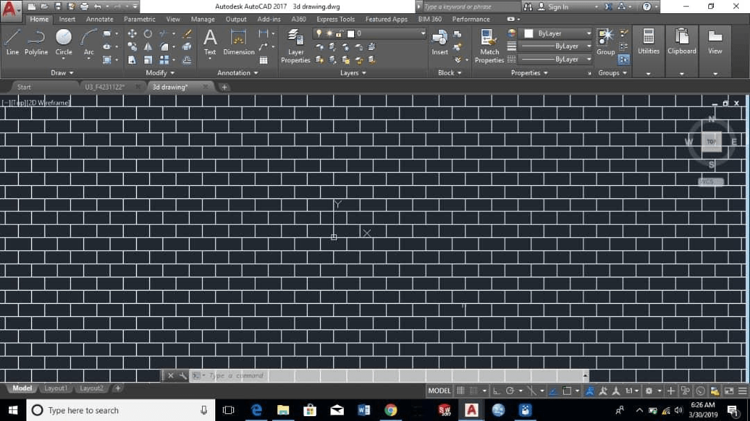
To begin, either enter the command wi or choose wipeout from the *draw* drop-down by typing wi.

By clicking and dragging your cursor, define the perimeter of the region to be destroyed.

To delete, use the Enter key.

A poly-line can be used to designate a wipeout boundary as well. Draw the poly-line object first, as seen below.
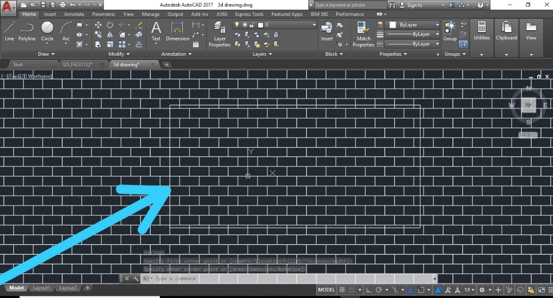
Select the poly-line object after selecting the wipeout tool from the draw drop-down menu or by typing *wi* (red arrow).

Entering will display the image below.
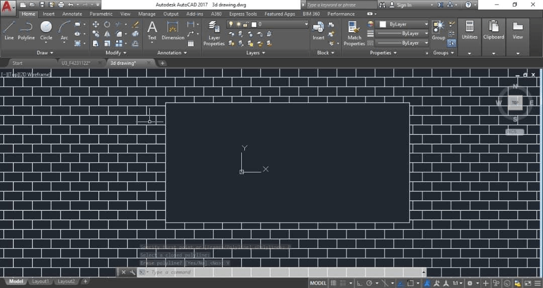
Type the wipeout command once more, choose *frame*, and then click *no* to make the Wipeout region's frame invisible. When you hit enter, you'll see the wipeout zone (seen below) without a frame.
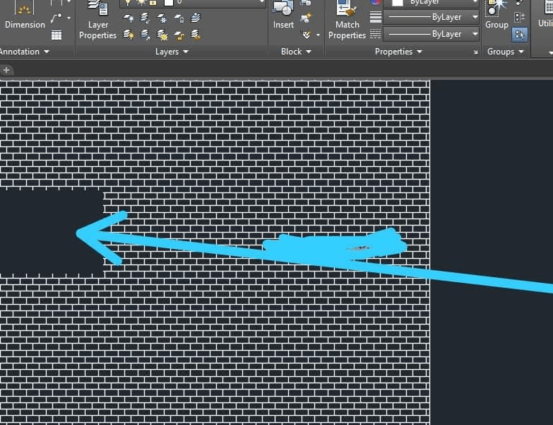
A circle or a filleted object cannot be used to generate a wipeout zone. However, it will resemble a circle if you choose a polygon with a lot of sides, say 30 sides. Choose the polygon tool, enter 30, and then choose "inscribe in a circle."
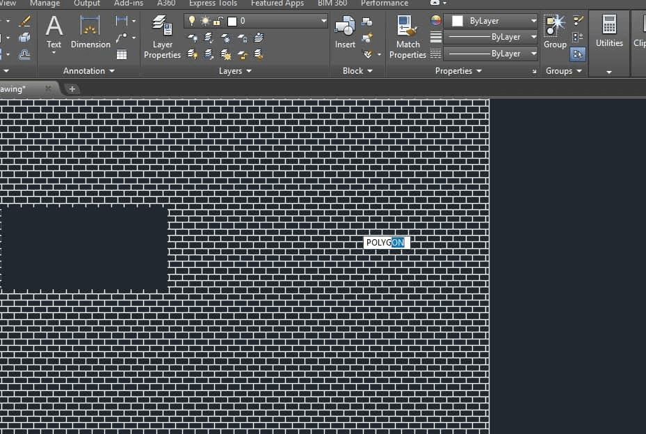
This polygon, which almost resembles a circle, will be yours.
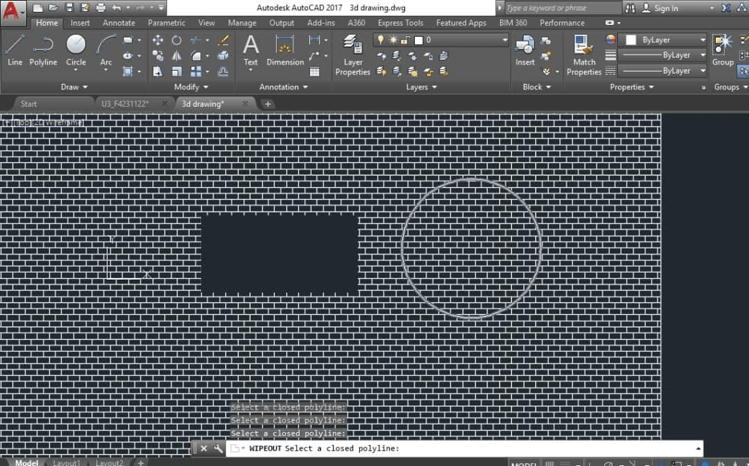
To get the image below, apply wipeout one more to the polygon.

Both rectangular and non-rectangular wipeout objects can be made. A polyline mode, which enables the creation of non-rectangular wipeouts, is by default enabled. By clicking on the black down-pointing arrow, the tool's submenu is accessed:
- Rectangle makes a rectangle in the wipeout. similar to the entity Rectangular, is added.
- Polyline is a non-rectangular wipeout is produced. is added similar to the Polyline object.
- Show displays all of the wipeout objects' boundaries in the active drawing.
- Hide removes all wipeout boundaries from the active drawing.
A non-rectangular wipeout should be added.
1. Choose PolyLine from the list by clicking on the black down arrow next to the button.
2. By left clicking anywhere on the drawing or using the dynamic input, specify the beginning point of the wipeout object.
3. To choose the second location, move the mouse to the side and then left-click.
4. To add a circular arc, right-click and choose Arc from the context menu.
5. Drag the mouse to designate the wipeout object's third point.
6. To add a line segment, right-click and choose Line from the context menu.
7. When finished, double-click.