
AutoCAD Mechanical
AutoCAD Mechanical is a complex add-on to conventional AutoCAD design and 2D drawing software that provides specific features for the manufacturing, engineering, and mechanical design sectors, as well as companies that employ digital prototype processes.
Clients may finish projects in considerably less time using AutoCAD Mechanical CAD software than they could with standard AutoCAD, decreasing project costs and improving profitability. AutoCAD Mechanical subscriptions are available in monthly, annually, and three-year increments, and it's also included in the Autodesk Product Design Collection and AutoCAD with specialized toolsets.
With over 700,000 mechanical parts and components, machinery generators, and calculators, as well as Autodesk Inventor Fusion, which allows intelligent re-use and direct manipulation of a variety of 3D file formats, AutoCAD Mechanical's powerful mechanical design and engineering biassed toolset simplifies and accelerates the design process.
Advanced drafting features like intelligent layer management, automated hidden line functionality, power dimensioning tools, and additional mechanically biassed drawing tools boost productivity even further, making AutoCAD Mechanical a must-have for mechanical design and engineering professionals who prefer a primarily 2D workflow.
Because AutoCAD Mechanical (ACM) is based on AutoCAD, you can accomplish whatever you can in AutoCAD Mechanical. It may take some searching, but it's there someplace. ACM also includes upgraded versions of regular AutoCAD commands that are used as defaults. Don't be afraid to try them; you'll fall in love with them. The "One" AutoCAD, as well as multiple suites and collections, includes AutoCAD Mechanical. It's possible that you already have it.
AutoCAD Mechanical
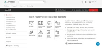
AutoCAD Mechanical is a design and manufacturing programme. If you're a mechanical or manufacturing engineer or designer, this is most likely the set of tools you'll use. It includes all of the basic AutoCAD tools, as well as libraries of standardized components and tools, including as bolts, bearings, and nuts, to help you get started quickly.
This implies that instead of drawing a circle, indicating the diameter, and extruding a cut to produce a hole for a screw, you can now only specify the center point of the hole and the bolt's reference (i.e., M5x10), and it will build the hole for you.
SolidWorks, which is another industrial-level application with its own toolbox, is a similar programme. Although it's more commonly used by amateurs, Fusion 360, another Autodesk product, is fantastic for mechanical modelling because it also includes assembly and simulation tools. Inventor, another Autodesk choice, is a prototype application aimed specifically at manufacturing designs.
Use Cases That Are Common & Popular
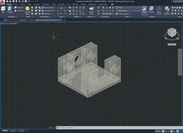
AutoCAD is unquestionably an industry standard, particularly in mechanical engineering, where it was initially designed. Any employer that wants design skills will almost certainly inquire about your AutoCAD knowledge when you apply for a job. If you have proper certification, that's even better.
Many fields of mechanical engineering utilize AutoCAD, notably the Mechanical toolset.
From bioengineering solution firms working on prostheses to developing thermic systems including boilers, cooling towers, and evaporative coolers. It's also worth noting that it's utilized for the whole design process, including strain and deformation simulation, rather than just the modelling and blueprint phases.
AutoCAD Mechanical has been used for many fascinating and spectacular projects, such as designing and building a solar farm, according to AutoCAD's Case Studies and Success Stories.
The Most Important Tools, Features, and Functions
Creating Layers
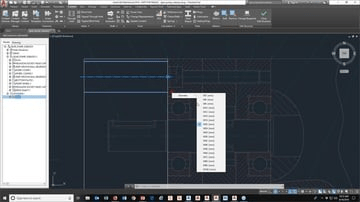
Because AutoCAD is mostly used for 2D modelling, you may organise your design in layers, just like you would for a Photoshop project. This can be used to distinguish developed parts from conventional parts such as bolts and nuts, or in a variety of different ways. Because this capability isn't widespread in design software, it can be a significant benefit.
Standard Parts Are Easily Accessible
For industry-standard parts, AutoCAD Mechanical has an easy-to-use mechanical toolbox. Programs like SolidWorks have had this feature since the beginning; however, AutoCAD Mechanical improves it by allowing you to use those components as a reference to automatically create holes and trees in addition to allowing you to add those parts.
Dimensions with Intelligence
While several applications provide "smart dimensioning," adding dimensions to AutoCAD Mechanical is genuinely intelligent. When you add them, you first choose a reference point, which may be a line or a Center point, and then just click on the additional lines you want to measure in relation to that initial point, and it will automatically add all dimensions. Other applications need you to choose both points each time a new dimension is added.
Formats for Documentation
Many of the standards you might be dealing with, such as DIN or ISO, have documentation and blueprint forms in AutoCAD Mechanical. So, if you have to submit designs in ISO format, you won't have to adjust parameters like arrow lengths, millimeters of gap between the drawing and the dimension quotation, or margin sizes because they're all pre-determined by the standard. Instead, all you have to do is adjust the format norm, and the specs will be updated automatically.
Bill of Materials (BOM) generator
You can count your parts and make a bill of materials (BOM), but that's not all. If you add a new component, it will be instantly added to your BOM without you having to edit it or remove and recreate it, and the layout will be preserved. That is, if your BOM is aligned with the bottom line of your blueprint page, it will know to go up without you having to manually adjust it, ensuring that the table does not cross that boundary.
Part References (or Components) and associated information make up the AutoCAD Mechanical Bills of Materials (BOM). The BOM is live in the sense that it updates as the drawing changes. The information on your components may include whatever you want to monitor, such as descriptions, material, and vendor.
STRUCTURE
ACM Structure is a mix of blocks and groups that defines components, similar to blocks on steroids. The components described by ACM are both parts and assemblies that form the structure of the assembly you are developing, despite being only 2D geometry. As you construct the structure, the BOM grows.
Help from the ACM... "Mechanical Structure combines the benefits of Blocks and Layer Groups, plus more. Because the mechanical structure is specifically created to organize a drawing. Beyond visibility benefits (provided by layer groups), reuse of geometry, and automated BOM updates (provided by blocks), the features are extensive."
More than 700,000 standard components and features
Create precise drawings using ISO, ANSI, DIN, JIS, BSI, CSN, and GB standards in mind. The Content Manager, which allows you to add a piece or feature to a content library, allows you to create and preserve unique material.
Dimensioning with power and automation
Make more progress in less time. Set options for power dimension commands for the current standard using shortened dialogue boxes.
Annotations/symbols for GD&T
Pre-configure symbols and save them in a symbol library for later usage. Symbol libraries for welding, surface texturing, and other topics are also available.
Leader's observations (AMNOTE)
Formulas that automatically apply to an object can help you get the most out of your notes. Instead of having to build it yourself, use a template from a preset collection to show important context-sensitive information right away.
Creating title and border blocks
To operate with your system, customize the drawing borders and title blocks. Each of these components is available as a separated file that you may copy and alter to improve your setup.
Detailed drawing
Use mechanical design-specific intelligent drawing software. Use reusable detailing tools like Centerline, AMSHIDE, Hole Charts, and Scale Area for Viewports to improve drawing productivity and efficiency.
2D calculations
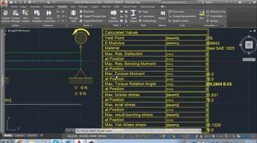
Combine autonomous part creation with drawing automation to maximise value. Analyze designs quickly and accurately using 2D calculations like as FEA, Shaft Calc, and Moment of Inertia.
Other Minor Details
- For overlapping components, AutoCAD Mechanical constructs concealed and dotted lines automatically. Although this isn't very novel, given that applications like SolidWorks have always done this when in drawing mode, it's still a nice touch. You may also select to view or conceal such lines to simplify the appearance of your design and make working with it easier.
- It features simulations for stress, strain, deformation, and a variety of other attributes to let you evaluate your design's capabilities.
- Custom components that you create can be saved in your own library for you and others to utilize.
- You can work on your designs even on the road using the AutoCAD mobile app.