
×

Rectangle command in AutoCAD

The rectangle command is used to create rectangles in our drawing.

We can create rectangles randomly by specifying the points and also by specifying the values of length and width.

METHOD 1:-

We can create rectangles by specifying the value of length and width.

The steps are given below:

  • Select the rectangle command from the ribbon panel. The rectangle icon will look like the below image:
Rectangle command in AutoCAD

Or
Type Rec or Rectangle in the command line and press Enter.

  • Specify the first corner point on the viewport.
  • Specify the length and breadth of the rectangle in the form of @length, width. For example, @4,5.
  • Where, 4 is the length of the rectangle, while 5 is the width of the rectangle.
  • Press Enter.

METHOD 2:-

We can also create rectangles randomly by specifying the points.

The steps are given below:

  • Select the rectangle command from the ribbon panel. The rectangle icon will look like the below image:
Rectangle command in AutoCAD

Or
Type Rec or Rectangle in the command line and press Enter.

  • Specify the first corner point on the viewport.
  • Specify the second corner point (diagonally opposite to the first point) on the viewport.

METHOD 3:-

We can create rectangle with rotation

  • Click Home tab > Draw panel > Rectangle.  Find
Rectangle command in AutoCAD
  • Specify the first corner of the rectangle.
  • Enter R for Rotation.
  • Enter the rotation value or enter P to pick two points to define the angle of rotation.
  • Specify the other corner

Rectangle with round corners

The rectangles can also be created with rounded corners.

The steps to create a rounded corner rectangle are listed below:

  • Select the rectangle command from the ribbon panel. The rectangle icon will look like the below image:
Rectangle command in AutoCAD

Or
Type Rec or Rectangle in the command line and press Enter.

  • Type F or Fillet and press Enter.
  • (Fillets are used to create round edges.)
  • Specify the fillet radius for the rectangle. For example, 1.
  • Press Enter.
  • Specify the first corner point of rectangle on the viewport.
  • Specify the length and breadth of the rectangle in the form of @length, width.
    For example, @6,6
  • Press Enter.

The rectangle formed is shown in the below image:
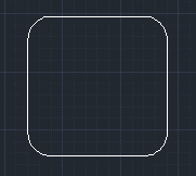
Rectangle command in AutoCAD

We can also type Elevation or E instead of Fillet to create rounded corners.

Rectangle with slanted corners

The rectangles can also be created with slanted corners.

The steps to create a slanted corner rectangle are listed below:

  • Select the rectangle command from the ribbon panel. The rectangle icon will look like the below image:
Rectangle command in AutoCAD

Or
Type Rec or Rectangle in the command line and press Enter

  • ype C or Chamfer and press Enter.
  • (Chamfers are used to create slanted edges.)
  • Specify the first chamfer distance for the rectangle. For example, 1.
  • Press Enter.
  • Specify the second chamfer distance for the rectangle. For example, 1.
  • Press Enter.
  • Specify the first corner point of the rectangle on the viewport.
  • Specify the length and breadth of the rectangle in the form of @length, width. For example, @7,6.
  • Press Enter.

The rectangle formed is shown in the below image:
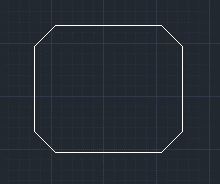
Rectangle command in AutoCAD

Rectangle with increased width

We can increase the width of the rectangle.

The steps to increase the width of the rectangle are listed below:

  • Select the rectangle command from the ribbon panel. The rectangle icon will look like the below image:
Rectangle command in AutoCAD

Or
Type Rec or Rectangle in the command line and press Enter..

  • Type W or Width and press Enter.
  • Specify the line width for the rectangle. For example, 1.
  • Press Enter.
  • Specify the first corner point of the rectangle on the viewport.
  • Specify the length and breadth of the rectangle in the form of @length, width. For example, @5,5
  • Press Enter

The rectangle formed (represented by blue lines for better visibility) is shown in the below image:
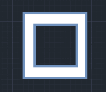
Rectangle command in AutoCAD

Rectangle with increased thickness

We can increase the thickness of the rectangle.

The steps to increase the thickness of the rectangle are listed below:

  • Select the rectangle command from the ribbon panel. The rectangle icon will look like the below image:
Rectangle command in AutoCAD

Or
Type Rec or Rectangle in the command line and press Enter.

  • Type T or Thickness and press Enter.
  • Specify the thickness of the rectangle. For example, 1.
  • Press Enter.
  • Specify the first corner point of the rectangle on the viewport.
  • Specify the length and breadth of the rectangle in the form of @length, width. For example, @6, 5.
  • Press Enter.

The thickness will be in the Z direction and visible in 3D only.


Related Topics

Create Block in AutoCAD

Blocks In AutoCAD, the term "blocks" refers to repetitive things that you insert in your designs. Symbols is another name for them. In AutoCAD, the words "Block Library" and "Symbol Library"...

3 minutes read.

Trim command in AutoCAD

TRIM (Command) You have two options for trimming objects: Quick mode and Standard mode. Quick Mode is the fastest mode. To trim items, individually select them, push and drag to start a...

6 minutes read.

Wipeout Command in AutoCAD

Use the Wipeout command to conceal some drawing elements without erasing them. It is a background-colored item with concealable edges that have a different hue. To conceal a region in a...

4 minutes read.

Extrude command in AutoCAD

In AutoCAD 3D, the extrude function is useful. Extrude pushes up the surface, creating a 3D solid from a 2D closed shape or a 3D surface from an object with open...

4 minutes read.

Point Command in AutoCAD

Points in AutoCAD 2D may provide excellent reference points for additional drawings. In this post, we'll demonstrate how to construct single and multiple points in AutoCAD 2D, along with the...

1 minute read.

Inquiry command in AutoCAD

Pick an inquiry type, then choose the data by following the on-screen directions. Once the investigation is complete, you may copy the data to another file, such a Microsoft Excel...

3 minutes read.

Subtract command in AutoCAD

In AutoCAD, use the subtract command. Use the subtract command in AutoCAD. By subtracting one set of existing 3D solids from a second, overlapping set, SUBTRACT may be used to...

3 minutes read.

Attedit command in AutoCAD

At the Command prompt, modify a block's attribute data. You may filter the properties that need to be changed based on the attribute tag, the current value, or the selected...

4 minutes read.

Hatch command in AutoCAD

In AutoCAD, the Hatch command is used to fill patterns inside an enclosed region. Hatched, gradient, and solid fill designs are available. A gradient pattern is a seamless transition between two...

5 minutes read.

Lisp command in AutoCAD

Can have AutoCAD automatically load LISP routines Issue: how to have AutoCAD automatically load AutoLISP functions. The program's files must be manually reloaded each time it is run. Solution: You may either utilize the...

4 minutes read.

AutoCAD Command

How to enter a command using the command line. Type a command on the command line. Choose one of the following options to run the command: Type the complete command name in...

9 minutes read.

Copy Command in AutoCAD

Using Two Points to Copy an Object Select the Home tab > Modify panel > Copy option.Press Enter after selecting the items to copy.Set a starting point for the copy.Make a...

3 minutes read.

AutoCAD Mechanical

AutoCAD Mechanical is a complex add-on to conventional AutoCAD design and 2D drawing software that provides specific features for the manufacturing, engineering, and mechanical design sectors, as well as companies...

6 minutes read.

Script Command in AutoCAD

What exactly is AutoCAD scripting? Scripting is another means of automating processes in AutoCAD that does not need the use of programming languages such as VBA or Auto LISP. Script files...

3 minutes read.

Dim command in AutoCAD

A single command may be used to create many dimensions and dimension kinds. Find You can choose one or more of an item's points to dimension it, and then click to establish...

4 minutes read.

3D command in AutoCAD

Below is a list of commonly used AutoCAD commands that are used when working with 3D solids. POLYLINE (PL) – You may generate a 2D polyline with the POLYLINE (PL)...

11 minutes read.

LINETYPE Command in AutoCAD

linetypes are loaded, set, and modified.    Find It displays the Linetype Manager. Options are shown when you use -LINETYPE at the Command prompt. linetypes are loaded, set, and modified at the command prompt. The following...

3 minutes read.

Stretch command in AutoCAD

How to use Stretch command in AutoCAD 1) This command in AutoCAD is excellent and helpful. Use the Stretch command to quickly move or alter any items, such as a door...

4 minutes read.

Dimension command in AutoCAD

To dimension an item, you can choose one or more of its points, and then click to set the dimension line. When you hover over an item, the DIM command...

8 minutes read.

Mesh Command in AutoCAD

It creates a 3D mesh basic object, such as a wedge, torus, box, cone, cylinder, pyramid, or other shape. Find Mesh primitives, or the fundamental mesh shapes, are comparable to the 3D...

6 minutes read.