74138 IC DECODER
74138 DECODER
Decoder A combinational circuit called a decoder can have up to 2n output lines and 'n' input lines. When a decoder is enabled, depending on the mix of inputs, one of these outputs will be active. This means that the decoder discovers a certain code. When the decoder is activated, its outputs are the minimum terms of 'n' input variables (lines). Some features of Decoder are:
- A Decoder converts an encrypted input signal to many output signals in another format.
- Encoder is the inverse of a decoder.
- A decoder is used to identify bits and encode data.
- In networking applications, decoders are widely used.
What is 74138 Decoder?
The 74138 is a three-to-eight-line decoder or multiplexer integrated circuit. This integrated circuit is ideal for high-speed bipolar memory chip select address decoding. The gadget is composed of a Schottky diode, which makes it fast and compatible with TTL ICs.
Specifications of the 74138 IC Decoder
- 4.5-5.5V power supply
- 5V is a typical voltage supply.
- 30MHz is the maximum clock frequency.
- -800µA high-level output current
- 16mA low-level output current.
- 2V high-level input voltage.
- Input voltage at low levels: 0.8V
- 5.2mA is the current rating.
- Propagation time: 18ns
- High velocity
- TTL compatible with low power consumption.
- High noise resistance
We use the well-known Integrated Circuit 74138 3 to 8 decoder. The integrated circuit has sixteen pins.
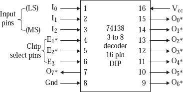
Three input pins, identified as I2, I1, and I0, are present and actively in the high state. The output pins, which are eight and categorized as O7*, O6*, to O0*, are actively in the low state.
The chip requires a grounded +5 V DC power source to function. The fact that just one output line is totally reliant on input pins I2, I1, and I0 should be highlighted.
Let us use the example where the output line O7* becomes 0, when we set pins I2 I1 I0 to 1 1 1. In the unlikely event that I2 I1 I0 = 0 1 0, the lines of output O2* shift to 0.
Additionally, the input activates the lines of output if and only if the 74138 chip is chosen. When E1* becomes 0, E2* becomes 0, and E3 becomes 1, the chip 74138 is chosen.
EPROM-7 is chosen when 74138 is chosen and A12 A11 A10 changes to 1 1 1. Following the selection of 74138 and this place in EPROM-7, a specific location in the address range from A9 to A0 is chosen. Consequently, the starting address becomes:
- From A15 to A13, choose 74138 0 0 1.
- From A12 through A10, choose an EPROM. 0 0 0
- It chooses a place in the EPROM from A9 to A0. 0 0 0 0 0 0 0 0 0 0 The final address bit pattern is therefore changed to 0 0 1 0 0 0 0 0 0 0 0 0 => 2000H.
In order to create Chip select logic, 74138 is used:
We create signals for chip selection in an eight-chip microcomputer system utilizing selection logic.
Let's say there are eight 1K x 8 sized EPROM chips, and we want the addresses to start at 2000H, 2400H, 2800H,..., 3C00H.
In the diagram below, 74138 is chosen when addresses A15, A14, and A13 change to 0 0 1. When 74138 is chosen and A12, A11, and A10 change to 0 0 0, EPROM-0 is chosen. The memory location in the EPROM chooses the address lines starting at A9-0 to be 0, after which 74138 and EPROM-0 get selected.
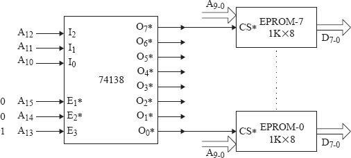
The following figure shows the address of starting for EPROM-0 as a result.
Here,
RAM is chosen by A15 to A11.
A10 to A0 selects a RAM location.
1 1 0 0 0 1 0 0 0 0 0 0 0 0 0 0 => C400H Following the completion of the 74138 selection, we choose EPROM-7.1 1 1, which is followed by A12 A11 A10.
Following the selection of 74138 and this place in EPROM-7, a specific location in the lines of address range from A9 to A0 is chosen.
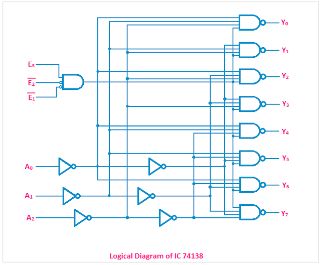
The IC 74138 Logical Diagram
NOT Gates and AND Gates are used in the logical circuit of the IC 74138. You can see the circuit diagram in the below figure.
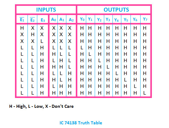
Truth Table for IC 74138
The truth table for IC 74138 is shown below.
74138 IC Operating Conditions
1.Vcc, or supply voltage, should be set between 4.75V and 5.25V.
2. Operating temperature range should be between 0 to 70-degree centigrade.
Disadvantages:
- We have separate circuits for chip selection if the 74138 is not used, leading to complex circuits.
- The circuit would be quite pricey.
IC 74138's characteristics
- It has a high-speed IC and is very quick.
- Because it is made up of low power Schottky diodes, it uses extremely less electricity.
- A demultiplexing facility is present.
- Its propagation latency is quite minimal.
- The right operating temperature.
Applications for IC 74138
1. The primary use of the decoder IC, is to decode digital signals.
2. Digital memory circuits employ them.
3. They are used in applications for data routing.
4. Digital signals are demultiplexed using them.