Instruction Cycle: Computer Organization and Architecture
What is an effective Address?
“Effective address is the address of operand in a computation-type instruction.” Computation type instructions are like ADD, SUB, MOV, OR, AND, etc., which require operand to operate. Whenever the operand is present, its address is known as its effective address.
or
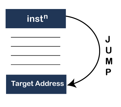
“Effective address is the target address in a branch type instruction.” Branch type instructions are like JUMP type of instructions. Suppose, if sequential instruction execution is stopped suddenly and it has to JUMP from one address to another. So, wherever (on an address) an instruction has to jump, that place is called target and its address is called as target instruction address also known as effective address in-branch type instruction.
Instruction cycle
If the CPU wants to execute one instruction, it must follow a series of 6 phases.
One instruction = 6 phases
Next instruction= 6 phases
Another next instruction= 6 phases
The CPU performs 6 phases to execute an instruction, and phases are repeated repeatedly. This cycle of phases is called as Instruction cycle.
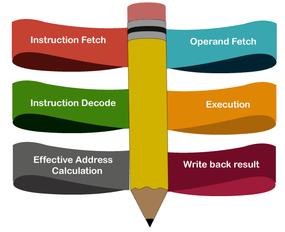
Six phases of the Instruction Cycle is divided into two parts.
a) Fetch cycle
- Instruction Fetch
b) Execution cycle
- Instruction decode
- Effective Address Calculation
- Operand Fetch
- Execution
- Write back result
The instruction cycle is explained with the help of an example.
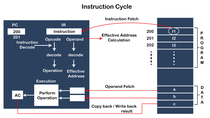
- Instruction fetch
It is the process in which we bring the instruction from memory to the CPU. When the CPU wants to execute the first Instruction I1 of the program, it fetches an instruction from memory to the CPU. For example, in the above figure, when the CPU wants to execute the first instruction, it must have a program counter having a value of 200. The next instruction is going to execute on address 200. CPU brings this instruction from memory, and it is stored in the Instruction Register.
IR ? Memory[PC]
Note: The value of the program counter increases by the same number of addresses on which the instruction is stored in memory. CPU wants to execute instruction I1 copied to CPU from memory, then the value of program counter increased, and it becomes 201.
2. Instruction decode
When instruction is copied to the instruction register from memory to CPU, it contains the instruction's opcode, which is decoded by CPU. When the CPU decodes the instruction's opcode and gets to know what operation to perform, this process is called Instruction Decode.
3. Effective Address Calculation
Every instruction has two parts, one is the opcode, another is operand information. Opcode has already been decoded by CPU, and now CPU decodes the operand information from where it obtained the effective address.
4. Operand Fetch
To execute the program, operands are needed, stored in somewhere memory in the form of data, and that are fetched by CPU from memory; the process is called operand fetch. For example, a, b is the data stored somewhere in the memory. It is fetched by CPU from memory.
5. Execution
When the operation is performed on data, and the result is generated to the Accumulator. This process is called execution. For example, the operation is performed on data a, b, and generated to Accumulator.
6. Write back result
Finally, after the result is generated in Accumulator, it is copied to destination c. the result is written back or copied back to the destination in memory.
Note: Every instruction doesn’t require all 6 phases every time. It depends on every instruction requirement; otherwise, by default, it is considered that all instruction requires 6 phases for execution.