BCD to 7 Segment Decoder
What is BCD?
BCD is called Binary Coded Decimal. As you know there are a lot of forms in which we can represent the number like Binary, decimal, hexadecimal, and octal etc.
In Binary format, we can represent any number with the help of just two numbers which are 0 and 1. It is also called base 2 format.
For example, to represent 12 in Binary we will write 1100, and to write 13 we will write 1101.
In decimal format we can represent any number with the help of 10 digits (0 to 9) and it is called the base 10 format. In the real world, we use the decimal format to represent any number, while the Binary number format is used by computers and electronic devices.
In BCD, we can represent the Binary equivalent of each digit of the decimal digit (0 to 9). To represent maximum value 9 we need 4 bits of Binary, so in BCD we used 4 digits to represent the equivalent decimal number.
Suppose four digits are A, B, C, and D where A is MSB (Most Significant Bit), and D is LSB (Least Significant Bit). Let’s see the BCD equivalent of each decimal digit:
| Decimal Digit | A | B | C | D |
| 0 | 0 | 0 | 0 | 0 |
| 1 | 0 | 0 | 0 | 1 |
| 2 | 0 | 0 | 1 | 0 |
| 3 | 0 | 0 | 1 | 1 |
| 4 | 0 | 1 | 0 | 0 |
| 5 | 0 | 1 | 0 | 1 |
| 6 | 0 | 1 | 1 | 0 |
| 7 | 0 | 1 | 1 | 1 |
| 8 | 1 | 0 | 0 | 0 |
| 9 | 1 | 0 | 0 | 1 |
Seven segment display
Seven segment is a special kind of electronics circuit that uses 7 LEDs to represent the digits from 0 to 9. As we know, Binary 1 means logic high or ON and Binary 0 means logic low or OFF. This same phenomena applies on 7 segment displays where different combinations of these 7 LEDs ON and OFF make the decimal number.
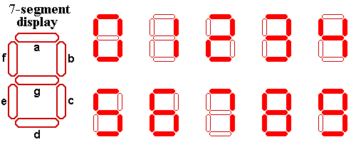
From the above image we can see the arrangement of 7 LEDs represented as a,b,c,d,e,f, and g.
These LEDs work in two modes:
1. Common Cathode Mode: In this mode, the cathode of all 7 LEDs is connected together and to blink any led, we have to set logic ‘1’ to its input pin.
2. Common Anode Mode: In this mode, the anode of all 7 LEDs is connected together and to blink any led, we will have to set logic ‘0’ to its input pin.
Generally, we use common cathode mode.
For making 0:
We will set the led a,b,c,d,e,f at logic ‘1’ and led g at logic ‘0’.
For making 1:
We will set led b,c at logic ‘1’ and the rest LEDs at logic ‘0’.
For making 2:
We will set led a,b,g,e,d at logic ‘1’ and res LEDs to logic ‘0’.
For making 3:
We will set led a,b,c,d,g at logic ‘1’ and led e,f, at logic ‘0’.
For making 4:
We will set led b,c,f,g at logic ‘1’ and rest led at logic ‘0’.
For making 5:
We will set led a,c,d,f,g at logic ‘1’ and rest led at logic ‘0’.
For making 6:
We will set led a,c,d,e,f,g at logic ‘1’ and rest led at logic ‘0’.
For making 7:
We will set led a,b, and c at logic ‘1’ and the rest led at logic ‘0’.
For making 8:
We will set led a,b,c,d,e,g at logic ‘1’ and rest led at logic ‘0’.
For making 9:
We will set led a,b,c,d,f,g at logic ‘1’ and rest led at logic ‘0’.
Decoder: decoder is an electronic circuit that can change one form into another form.
The decoder has some input pins and some output pins to get the desired output.
BCD to 7 segment decoder has 4 input pins to take input as BCD number and generate the output as 7 segment value which has 7 digits, so it has 7 output pins.
Using k Map will get the equivalent simplified combination of BCD digits to decide when each digit of LED is going to be set.
To set a: A + C + BD + BD
To set b: B + CD + CD
To set c: B + C + D
To set d: A + BD + BC + CD + BCD
To set e: BD + CD
To set f: A + BC + BD + CD
To set g: A + BC + BC + CD
The 7-segment display and the decoder are generally used in calculators or in some digital watches.