
Control Unit Organization
Control Unit Organization
The Control Unit is the unit in the CPU, which controls the various components like input & output devices, logic unit and memory. The Control Unit is the circuitry that controls or directs the component’s operations and tells them how to respond to the instruction received from the program.
Functions of the control unit
CU's main function is to direct the operations during the execution of a program by the processor.
The control unit converts the input into control signals sent to different components and registers to execute its functioning.
The Control Unit cannot store or process the data; it just directs the data signals.
Control unit directs working of all its components. It provides direction to the control signals and send them to the appropriate component to execute the instruction. Control unit components are:- control signal within the CPU, instruction register, input flags, control bus, clock signals, control signals to/from the bus.
Design of Control Unit
Every CPU can be designed in a different- different way, same with the control unit. Control unit can be designed in two possible best ways.
- Hardwired Control Unit
- Micro-programmed Control Unit
Hardwired Control Unit
As the name defined hardwired control unit, going to design the control unit by using the hardware (circuits). The control logic is implemented with Gates, flip-flops, decoders, and other digital circuits in this type.
“Control logic is the unit which generates the control signals which are implemented using the hardware that’s why it is called as hardwired control unit.”
Advantage: Hardware is always faster. Due to this, it can be optimized to produce a faster mode of operation. It generates the fastest control signal.
Disadvantage: a) If CPU design is very complicated or very much modern, hardwired control is difficult to implement
b) Rearranging the wires among various components is difficult.
c) In the hardwired control unit, updation in the control logic is difficult. For example, the CPU has generated a control signal/ control word. The signal goes to registers (R1, R2, R3…), ALU, Memory (Read and Write signals); if a little bit design of the CPU has changed, then the CPU way of operating will also change. The operating method will be updated, and due to this, the control signal/control word will be different. Control signals format changes when we change the hardware circuit, which create difficulty.
From the diagram, we explain the working of the hardwired control unit.
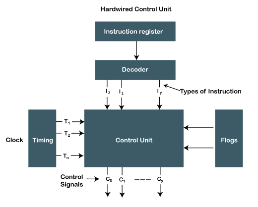
Working of a hardwired control unit is explained with the help of an example:
Suppose,
Step 1) A CPU can execute some 16 different instructions (I1, I2, I3, I4,…….I16).
Step 2) CPU executes each instruction distinctly, each instruction is executed in a different method to others, and it is done by executing small-small micro-operations for each instruction.
Assume, CPU executes instruction 1 with 8 distinct micro-operation. So to execute I 1completely, 8 cycles are required by CPU.
I 1=> ?opn 1, ?opn 2, ? opn 3, ?opn 4 ….. ? opn 8
For the second instruction, 6 cycles are required.
I 2=> ?opn 1, ?opn 2, ? opn 3, ?opn 4, ? opn 5, ? opn 6
Same, for completing one instruction, the different or same number of the cycle are required by CPU.
Step 3) For performing one micro-operation, CPU control unit needs to generate a set of control signals called control words.
?opn 1= 010010001001(1 C.W)
?opn 2= 1 C.W
?opn 3= C.W
?opn 4= 1 C.W
?opn 8=1 C.W
For each micro-operation control, the word will be different, but some signals are enabled in each control word, and some are disabled, and the control unit decides all these signals.
Step 4) One instruction is generated with micro-operation cycles, which are controlled by the control unit. The Control unit decides at what time which instruction is enabled or disabled. It is discussed in the table:
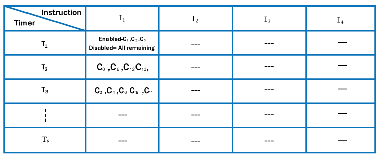
One who designed the CPU only knows which signal is to be enabled or disabled. After completing the table, the hardware is designed. After the execution of 1st instruction completely, the timing generator is reset for the second instruction as per the micro-operation cycle is required to complete the second instruction.
Micro-programmed Control Unit
In this control, logic is implemented with micro-programs. That's why it is called a micro-programmed control unit. It’s a midway between hardware and software.
“All possible control words are stored in a memory because it is a part of control unit) and based on the requirements, the specific control word is fetched from memory, then its signals are sent to different components.”
In this type, the control word is used to store the control signals encoded during the execution of a program and control words are stored in the memory. Memory can be easily changed; we can change the value (0 or 1) in the control word, enabling and disabling signals. We do not need to change the whole control word format as it can work on a variable format of 16-64 bit, or we can easily update the control logic.
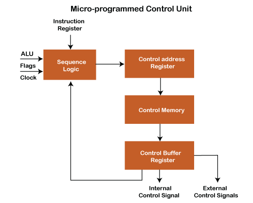
The sequence logic inputs are given by ALU flags, clock pulses and instruction register, which holds the instructions to be executed from the above diagram.
Instruction register-The instruction register sends data into sequence logic, and data is further sent to the control address register sequentially.
Control address register holds the address of the instruction/ control word data sequentially, sent by sequence logic. It holds the control word signals to execute the instruction and send them to control memory. It also helps to specify the address of the next micro-instruction to be executed.
Control memory is just a ROM (read-only memory). Control memory cannot perform any operation, and it's just read the data and stores the data input. Content of given control word in ROM at a given address specifies a micro-instruction required to execute the instruction. So, "A series of micro-instruction is stored in ROM." One instruction can be executed through the number of micro-operation/instruction cycle. Control memory used for another purpose also for example:-
- Control memory is used to fetch, generate instruction from the main memory.
- Used to evaluate effective address.
- Execute the specified operation.
- Store written operation used to fetch instruction.
Control buffer register- Data read from control memory is stored in the control buffer register, which sends internal and external control signals with which microinstructions are executed. Control buffer register sends a signal to sequence logic to execute the next instruction, and the same further process is carried out to execute the instruction.
Types of the micro-programmed control unit
- The horizontal micro-programmed control unit
- The vertical micro-programmed control unit
Advantage of MP control unit: Updating the control logic is easy as all the control signals are stored in memory, easily changed according to instruction requirements.
A micro-programmed control unit is implemented in high-level computers because it is easy to design, test, and implement.
The MP control unit's disadvantage is slower than the hardwired control unit because here, we have more flexibility in design.
Difference between Micro-programmed Control and Hardwired control unit
| Hardwired Control | Micro-programmed Control |
| Hardwired control unit technology is circuit-based. | Micro-programmed control unit technology is software-based. |
| Flip-flops, gates, decoders etc., are used in the implementation. | In controlling the execution of instructions, signals are generated by microinstructions. |
| It uses the fixed instruction format. | It uses the variable instruction format (16-64 bits per instruction). |
| Instructions are register-based. | Instructions are not register-based. |
| For information and data (instruction), ROM (Read Only Memory) is not used. | For information and data (instruction), ROM (Read Only Memory) is used. |
| The hardwired control unit is used in RISC. | The micro-programmed control unit is used in CISC. |
| It does decoding at a very fast rate. | It provides slow decoding. |
| It isn't easy to modify, as it follows a fixed instruction format. | It is easy to modify as it follows a variable instruction format. |
| It has less chip area. | It has a large chip area. |
How exactly are the control words stored?
Suppose CPU has = 16 instructions (I 1 to I 16)
For each instruction = 8 micro-operations ( 8 control words are required to generate one set of instruction)
In the control memory, whenever you are storing the control word, store each control word in a sequence required to execute one instruction like to execute I 1 type instruction 8 control words are required which are stored in sequence in the control memory. Same with the instruction I 2, I 3…I 16.
Total control words in memory = 16 x 8
= 27 = 128
Control memory address size = 7 bits.
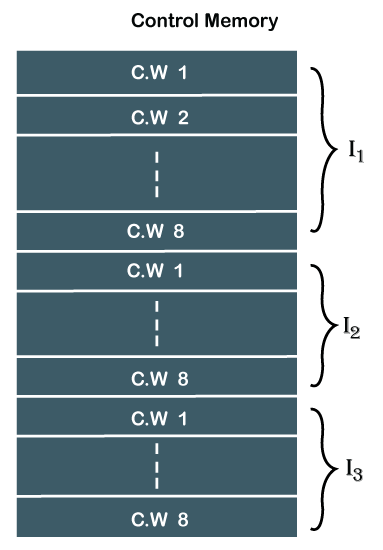
Note: It's mandatory to store all the control words required for instruction (I 1, I2…) in a sequence manner. Because whenever the CPU's control unit understands that it has to execute I 1 instruction afterward, the control unit is not dependent on any external thing. The control unit doesn't need to take any external input to execute the I 1 instruction, and it sends control word signals one by one in a sequence manner.