What is a Serial Port in a Computer?
A serial port on a computer is an interface for serial communications that allows data to enter or exit sequentially, one bit at a time. A parallel port, on the other hand, sends several bits concurrently in parallel. For the majority of the development of personal computing, information has been exchanged between computers and devices like modems, terminals, and other peripherals via serial ports.
Although serial ports can also be found on interfaces like Ethernet, FireWire, and USB, the phrase "serial port" often refers to hardware that complies with RS-232 or a similar standard like RS-485 or RS-422.
Higher-speed protocols, namely USB, have superseded serial connectors on modern commercial personal computers (PCs). Nonetheless, applications including point-of-sale systems, scientific equipment, industrial automation systems, and some consumer and industrial goods still often employ serial ports as they require straightforward, low-speed interfaces.
While networking technology (such as switches and routers) frequently uses serial interface ports for configuration, diagnosis, and unexpected repairs access, server computers may utilize them as control consoles for diagnostics. USB-to-serial converters may quickly add an Ethernet port to a contemporary PC so that it can communicate with as well as additional devices.
Hardware
To create a serial port, modern devices employ an integrated circuit known as a UART. This IC implements the time and data framing provided by the serial interface in circuitry by converting symbols to and from delayed serial form. When an IBM PC has a serial port, it uses any number of UARTs to implement it.
Alternatively, very low-cost systems, like some early return home computers, might employ the bit-pounding approach to use the Microprocessor to send the information through an output pin. The proprietary serial connectors on these early personal computers frequently had pinouts and voltage ratings that were incompatible with RS-232.
Prior to the widespread usage of UARTs due to large-scale integration (LSI), serial ports were frequently found in mainframes and miniature computers, which included several small-scale integrated circuits (ASICs) that implemented shift registers, logical gates, counters, and other necessary functionality. Serial ports were first added to the Super I/O device and, subsequently, the chipset as PCs advanced.
DTE and DCE
The outputs of a single device must be linked to the inputs of both of them when connecting two since each serial port signal is unidirectional. Data terminal machinery (DTE), in addition to data circuit-terminating device (DCE), are the two categories into which devices are separated. A straight copper cable, over which every individual pin on one end of the cable is linked to the same numeric pin on the other, may be used to connect a DCE device to a DTE device. This is because a line that constitutes an output on one device is a source of information on another, and vice versa.
Typically, peripherals like modems are classified as DCE, whereas computers and displays are classified as DTE. A cross-over, roll-over, or null modem cable which switched TX and RX lines must be used if it's essential to link two DCE devices.
Serial port connections are often gendered, meaning that they can only pair with other connectors of the same gender. When using D-sub-miniature connectors, the female connections have matching circular sockets, while the male connectors have projecting pins. These connectors can be used to terminate cables or place them on panels or equipment.
Male connections are more likely to be found installed on DTEs than female connectors on DCEs (the connectors on cables are the opposite). This is by no means ubiquitous, though; for example, the majority of serial printers are DTEs, even though they have a female bank25 connection. In this case, the mismatch can be fixed by using a gender changer or the cable's suitably gendered connections.
Linkages
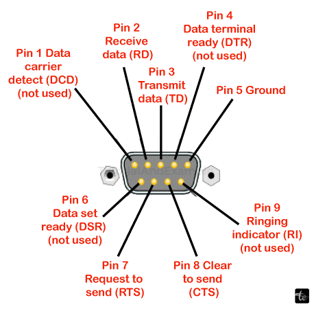
The 25-pin D-sub-miniature connection was the sole one included in the initially developed RS-232 standard, although a variety of different connectors have been employed for a variety of purposes, including cost and space savings. Specifically, connections with smaller pins are frequently utilized since numerous gadgets do not employ all 20 signals required by the standard. Numerous additional ports have been employed to provide RS-232 connections, some of which are shown in the following samples.
Since the Sequential/Parallel Adapter alternative for the PC-AT, when a serial and parallelism port could fit on the same card, the majority of IBM-compatible PCs have utilized the 9-pin DE-9 connection. The TIA-574 standard has been established for this connection for RS-232.
Graphing calculators and handheld unlicensed and two-way radio equipment are two examples of miniaturized devices with serial ports that use phone connections. These connectors are typically smaller, 2.5 or 3.5 mm, and feature a three-wire interface (transmit, receive, and ground).
Numerous gadgets also make use of 8P8C connections. The EIA/TIA-561 standard specifies a pinout utilizing this connector; however, Unix machines and network devices, including Cisco Systems equipment, often utilize the rollover cable, also known as the Yost standard.
The associated RS-422 standard is preferred by many Macintosh models, which mostly use circular mini-DIN connections. While the Macintosh came with two conventional ports for connecting a printer and modem, certain PowerBook laptops only have one combination connector in order to conserve space.
Another popular connector seen on baseboards and add-in cards is a 10 x 2-pin header, which is typically converted to the more common 9-pin DE-9 connector via a ribbon cable (and often put on a vacant slot plate or other section of the chassis).
Signal Ground, which is the same signal as the other connections but occurs on two of the pins in the Hdl standard, serves as a common return. The second Protective Grounded on pin 1 of the DB-25 connection is meant to be linked by every component to its frame grounded or something similar. While it is normal practice, connecting Protector Ground to Communication Ground is not advised.
Abstraction of Hardware
Rather than forcing programs to refer to a computer's serial ports by hardware address, operating systems typically provide them with symbolic names.
The /dev/tty* is the typical label for serial port devices in Unix-like operating systems. The term "TTY" is a widely used, trademark-free acronym for "teletype," a device that was frequently connected to serial ports on early computers. The character "*" indicates a string that uniquely identifies the port, with the format of the string varying depending on the device and operating system. Linux assigns the name /dev/ttyS* to 8250/16550 Serial hardware serial ports, /dev/ttyUSB* to USB adapters, and a variety of virtual serial port names that don't always begin with tty to various sorts of virtual serial ports.
Typical Uses for Serial Ports
Some of the more popular devices that are linked to a PC's serial port are included in this list. While some devices, like modems and serial mice, are becoming less common, others are easily accessible. The majority of microcontroller types have serial ports, which are used for communicating with other serial devices or a PC. Most typical uses of serial ports are as follow:
- Modems that dial up.
- Administration and configuration of networking hardware, including firewalls, load balancers, switches, and routers.
- GPS receivers (usually at 4,800 bit/s, NMEA 0183).
- Scanners for bar codes and other POS equipment.
- Text displays using LED and LCD.
- Low-speed satellite modems, satellite phones, and more satellite-based transceiver devices.
- Flat-panel displays that can be controlled using remotes, other AV equipment, or an external computer.
- Test and measurement tools include weighing systems and digital multimeters.
Certain applications exploit a serial port's control lines to monitor other equipment without transferring serial data since any digital signal may trigger the port's control signals. This idea was frequently employed in the commercial world for uninterruptible power supply models that used the control lines to indicate low battery life, power loss, and other information regarding status. The current state of the bits of the serial connector could be collected very quickly and at predictable periods, allowing the software to decode Morse code; at least some of the Morse code programs for training employed a code key attached to the wireless port to imitate genuine code use.
Configurations
Serial standards support numerous operating speeds, and the protocol can be modified to accommodate various operating environments. The settings that are most commonly used include speed, parity, number of break bits per character, and number of data bits per character.
A UART chip is used in current serial ports, and all these parameters are controllable by software. On circuit boards with hardware from the 1980s and earlier, jumpers or switches may need to be set.
The 9600/8-N-1 arrangement, which is often used for serial ports intended for PC connections, has emerged as the de facto standard.
Quickness
Because serial ports employ two-level (binary) signalling, the symbol rate in baud and the data throughput in bits per second are equivalent. The effective data rate is less than the bit rate at which it is transmitted since the overall speed includes bits for formatting (stop bits, parity, etc.). For instance, only 80% of the pieces are accessible for data when using 8-N-1 character framing; two additional framing bits are delivered for every eight words of data.
Some serial ports allow for the selection of several arbitrary rates; nevertheless, for data to be received successfully, the speeds on both ends of the connection must match. A common series of speeds is based on multiples of speeds for electromechanical teleprinters. Seventy-five 110 300 dollars, the years 1200, 2400, 2500 57600, and 115200 bit/s are among the bit rates that are often supported. Numerous common mobile baud rates include multiples of 0.9 kbps (such as 19200, 38400, and 76800) or 1.3 kbps (such as 57600, 115200). Crystal oscillators tuned at 1.843200 MHz are available for purchase expressly for this use. A serial port circuit may readily split down into smaller frequencies as needed, and it is 16 times faster than the fastest bit rate.
Bits of Data
Each character can have five data bits for Baudot coding: six (rarely used), seven (real ASCII), eight (for most types of data, as this number corresponds to a byte), or nine (rarely used). In most modern applications, eight data bits are utilized. Generally speaking, 5 or 7 bits are only useful with outdated technology like teleprinters.
The least important bit of each byte's data is sent first in the majority of serial communications architectures. The bit with the greatest importance first is another option. However, it is only sometimes utilized; the IBM 2741 publishing terminal was one example of this. The host system determines the bit order rather than its serial port interface most of the time. Local software can rearrange the bits in each byte both before and after transmission in order to connect with systems that have different bit ordering requirements than the local default.
Equitable
One way to identify transmission issues is through parity. In order to ensure that the total amount of 1 bit for every character containing the parity bit remains either continuously odd or always even, an additional data bit is transmitted with each information character when parity is utilized with a serial port. A byte is corrupted if it is received with an incorrect number of 1s. The presence of corruption does not always imply correct parity, as a corrupted message with an even proportion of mistakes will nonetheless pass the equality check.
Error correction cannot be implemented on a per-character basis with a single parity bit, and protocols used for communication over serial data lines usually have higher-level techniques to guarantee data integrity and request restoration of data that was accidentally received wrongly.
Each character's parity bit can be configured to a single of the following values:
- When a transmission is abbreviated, and there is no parity bit delivered, it is indicated by None (N).
- When the bit for parity is configured to produce an odd amount of 1 bit, the result is an odd (O).
- If the bit that determines parity is set to ensure that a set of bits beginning with 1 is even, the result is an even (E).
- When a parity bit is set to the marking signal situation (1-bit value), it is referred to as mark (M) parity.
- The parity bit is always sent in the spaced-out signal state (0-bit value) when using space (S) parity.
Since odd parity guarantees that every character experiences a minimum of one state change, it is more effective than even parity in identifying faults such as those that may arise from mismatched serial port speeds. Nonetheless, the most used parity option is none, in which case a communication protocol handles error detection.
Electromechanical teleprinters were set up to display a particular character when received data included a parity fault, allowing for the identification of communications damaged by line noise.
Stop Portions
The receiving signal circuitry can recognize when a character has ended and resynchronize to the character stream thanks to the stop bits that are supplied at the conclusion of each character. The one-stop bit is typically used in electronic equipment. It could be necessary to utilize one and a half or two stop bits if sluggish electromechanical teleprinters are employed.
Standard Notation
The framing of the serial connection is specified by the usual notation data/parity/stop (D/P/S). 8/N/1 (8N1) is the most widely used protocol for microcomputers. This indicates one stop bit, no parity, and eight data bits. The bit that determines parity is not one of the data bits in this notation. With an even equalization bit added to the seven data bits, there are eight bits total at both the beginning and stop bits, or 7/E/1 (7E1).
Additional signals are used for hardware handshaking; these are frequently the RS-232, the use of RTS or DTR/DSR message circuits. When storage space is about to fill, for example, RTS and CTS function to notify that data flow is being controlled. DTR and DSR are typically declared at all times to indicate that the gadget is present and switched on in accordance with the RS-232 norm and its successors. Nevertheless, there are non-standard implementations as well; printers that employ DTR for flow control are one example.
For instance, ASCII control letters XON/XOFF are used in software handshaking to regulate data flow. The XON & XOFF characters, which point in the opposing direction of the data being transmitted, are sent from the other end to the transmitter to regulate when the transmitter sends data. When the system first boots up, transmitting is permitted. The receiver notifies the sender to cease delivering data by sending the XOFF character when the receiver's queues are almost full. Subsequently, the receiver signals to the sender to continue transmission by sending an XON character once it has finished filling its buffers. This is an illustration of in-band signalling, in which the data and control information are sent over an identical channel.
Hardware handshaking has the advantages of being stateless, able to operate at very high speeds, and not being affected by externally imposed meanings on the transmitted data, such as ASCII. Its drawback is that additional hardware and cabling are needed, and the hardware touching protocol must be supported on the two sides of the connection.
One benefit of software handshakes is that they can function even in the absence of hardware touching circuits and cabling that are incompatible. The drawback of full in-band control signalling is that it makes it more difficult to make sure that control signals always pass through even when messages containing information are stopped and that data is always clear with control signals. The device driver or operating system often handles the former; the latter is typically handled by making sure that control messages are intentionally left out or escape (like in the Frog protocol) (such as in the American National Standards Institute terminals control).
An overrun receiver may be unable to grab data from the transmitting device if handshaking is not used. Using delays after lengthy tasks (like in Termcap) or using a mechanism to send data that was never received correctly (like TCP) are some ways to prevent this. Other strategies include increasing the total number of barriers so the receiver can keep up produced over a longer period or decreasing the latency of the connection's transmission so that it can always keep up.
Shake Hands (Computer)
A handshake in telecommunications is an automatic negotiating procedure that sets the guidelines of the link to communicate at the beginning of a conversation between two parties (for example, "Alice and Bob") by exchanging information. When a computer tries to interact with another device, the handshaking procedure is typically used to set communication guidelines. To create a communication link, two devices typically exchange signals. For instance, when a computer talks to a modem or other device, the two will communicate with each other to agree on the protocols to use and to let each other know when they are powered on and prepared to function.
Handshaking can negotiate settings like as information transmission rate, coding script, parity, interrupt mechanism, and other hardware features that are acceptable to devices and systems on either side of the communication channel. A method to communicate between two separate things is the handshaking. Nonetheless, the TCP three-way agreement is most frequently referred to as a "handshake" in TCP/IP RFCs. For example, RFCs pertaining to SMTP and FTP do not include the phrase "handshake." Transport Layer Security (TLS) configuration for FTP (RFC 4217) is one example. FTP RFC 3659 uses the term "conversation" instead of "handshake" to refer to the exchange of instructions.
All that would be required of the receiver in a basic handshaking protocol would be to say, "I read your last communication, and I am now ready for you to provide me with an additional one." A more intricate handshaking protocol may enable the sender to inquire as to whether the recipient is prepared to receive, or it might allow the recipient to respond negatively, indicating, "I haven't gotten your last email correctly, please resend it," if the data was damaged during transmission.
Connecting somewhat diverse systems or equipment via a communication channel is made easier by handshaking and eliminates the requirement for human interaction to establish parameters.
The acknowledgment messages in this configuration return to the seeking server to inform it that the message has been received, but the synchronize messages function as service inquiries from a single server to the other.
TLS Greeting
The record encodes a "control" protocol, the initial handshake transmission protocol (content type 22) when a transport-layer security (TLS) connection starts. In order for TLS to share the actual application data, all the information needed by both parties is exchanged over this protocol. It specifies how these messages are formatted or include this information, as well as how they are sent in order. These differ according to what the user and server require; that is, there are several ways to establish the connection. After this first exchange, there is either a warning signal (as described below) or an acceptable TLS connection (both sides are prepared to communicate application data over TLS).
Modems for Dial-up Access
Dial-up modems are a classic example of handshaking in action; they usually negotiate communication parameters during the initial establishment of a connection and then use those parameters to provide the best possible information transfer over the channel based on the channel's quality and capacity. When a connection is made, some modems with speaker output make what sounds like "squealing" (which actually refers to a sound that changes pitch 100 times per second). This is actually the sound of a modem at both ends communicating in a handshaking procedure; depending on the operating system or application controlling the modem, the speaker may be silenced once the procedure is finished.