
IEEE Standard 754 Floating Point Numbers
Floating Point Representation: IEEE- 754
There were many problems in the conventional representation of floating-point notation like we could not express 0(zero), infinity number. To solve this, scientists have given a standard representation and named it as IEEE Floating point representation.
IEEE stands for “ The Institute of Electrical and Electronics Engineers." It's an association that develops, defines and reviews the standard of electrical and computer science engineering. IEEE in 1985 and augmented in 2008 provided a standard to represent floating-point numbers and process them. This standard is now used by all the manufacturers while designing the floating-point arithmetic units to be portable among computers.
History of IEEE Floating Point Standard 754 -1985 & innovation in 2008
In the mid-'50s, floating-point binary numbers were used in the beginning without a format. As there was no defined format to represent floating-point numbers in computers, creating problems in the portability of programs from one manufacturer's computer to another manufacturer's computer. With the innovation of personal computers in the mid-1980s, the number of bits used to store floating-point numbers was standardized as 32 bits. After that, a standing committee was formed by IEEE to standardize how floating-point binary numbers would be represented in computer and to resolve exception conditions such as an attempt to divide by 0, representation of infinity,0 and uniformity in rounding numbers.
Now, the system was able to use standard floating-point formats in 32 bits and 64 bits. With the innovation in computer technology, it became feasible to use many bits for floating-point numbers. IEEE 754 standard was updated in 2008 with a new standard for 16 bits and 128 bits numbers. The new version IEEE 754-2008 stated the standard for representing decimal floating-point numbers.
IEEE 754 standard has given the representation for floating-point number, i.e., it defines number representation and operation for floating-point arithmetic in two ways:-
- Single precision (32 bit)
- Double precision ( 64 bit )
Single-Precision -
- Sign- In single precision, 1 bit is assigned for the sign (positive or negative).
- Exponent- 8 bit is assigned for the range named exponent.
- Mantissa- 23 bit is assigned for the precision ( it's for the fractional part)
Note:
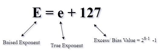
Why do we add 127?
Suppose a floating-point number:
1.1011 * 2+5 E = 5 + 127 = 132 positive
1.1011 * 2-5 E = -5+ 127 = 122 number
To maintain the +ve exponent only, we have to add 127 & 1023 (due to this, exponent always remain positive). If we add number less than 127, then we attain – ve exponent.
Note:- (i) If a different sign for exponent is used while performing the floating-point arithmetic, the hardware only concentrates on the exponent sign to overcome certain hardware problems in the floating-point representation. The true component is added to 127 to manage the number in + ve form. End-user subtracts 127 when we give E' to end-user.
In double-precision (64- bit)
- Sign- In single precision, 1 bit is assigned for the sign(positive or negative).
- Exponent- 8 bit is assigned for the range named as an exponent.
- Mantissa- 23 bit is assigned for the precision ( it's for the fractional part)
Excess = 2n-1- 1
In single precision In double precision
N= E = 8 N= E = 11
So, Excess = 28-1- 1 = 127 So, Excess = 211-1- 1 = 1023
What is the range of E & e?
E = 8 bit (in single precision format)
So, maximum value of a 8 bit number = 28 – 1= 255
Minimum value of a 8 bit number = 0
0? E ? 255 (because using 8 bits, total combination become = 28 =256[0-255]
But in actual the value for normal number 1? E ? 254
Therefore, 0 & 255 are reserved for special number.
Example:- Represent the following number in single precision and double precision.
- (-23.875)10
- (.75)10
Solution:- (-23.875)10 = -(10111.111)2 = -1.0111111 * 2+4
Mantissa
In single precision
S= 1 ( because number is –ve)
E= e + 127 = 4 +127 =131 =(10000011)2
M= 0111111
| S= 1 | E =10000011 | M=0111111….. |
1 bit 8 bit 23 bit
In double precision
S= 1 ( because number is –ve)
E= e + 1023 = 4 +1023 =1027 =(10000000011)2
M= 0111111
| S= 1 | E =10000000011 | M=0111111….. |
- bit 11 bit 52 bit
Q) (.75)10
Solution:- (.75)10 = -(.11)2 = 1.1 * 2-1
In single precision
S= 0 ( because number is +ve)
E= e + 127 = -1 +127 =126 =(01111110)2
M= 10000….
| S= 0 | E =011111110 | M=10000……. |
1 bit 8 bit 23 bit
In double precision
S= 0 ( because number is +ve)
E= e + 1023 = -1 +1023 =1022 =(11100011110)2
M= 100000…..
| S= 1 | E =11100011110 | M=100000….. |
1 bit 11 bit 52 bit
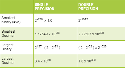
The maximum value in single precision
As we want maximum value so the number should be positive, i.e., S=0
E max= 254 = (11111110)2
M max = 11111…….111(23 bit)
V= (-1)5 (1.11111…..)2 x 2e where e = E-127
V= (-1)0 (1.11111…..)2 x 2254-127
V= (1.11111…..23 times)2 x 2127
V= ( 20*1 + 1 * 2-1 + 1 * 2-2+………..1 * 2-23) x 2127
V= ( 1+ ½ + ½2 +½3………..½23 ) x 2127
G.P series with r = ½, a =1, n =24[0-23]
Sum of G.P Series = a(1-rn) / 1-r = 2 x[1-2-24]
V= 2 x(1-2-24) x 2127
= (2-2-23) x 2127 = 3.4 x 1038
Minimum value in single precision
As we want maximum value so the number should be negative i.e. S=1
E min= 254 = (11111110)2
M min = 11111…….23 times(23 bit)
V= (-1)5 (1.11111…..)2 x 2e where e = E-127
Answer = -3.4 x 1038
Maximum and Minimum value in Single and double precision
IEEE -784 Floating-Point Standard –New Version (2008)
IEEE 754 standard was updated in 2008 with a new standard for 16 bits and 128 bits numbers. These are made to solve exact decimal computation required in financial transactions and for working in the graphic area, and using high-performance computers for intensive numeric computation.
16-bit Standard Representation
| Sign | Exponent | Significant |
| I bit | 5 bits | 10 bits |
The maximum positive integer is
+ 1.111..1 × 2 15
= 1 + (1 – 2– 11)×2 15
= (2 – 2–11)×2 15
? 65504.
The minimum positive number is
+ 1.000 … 0 × 2 –14
= 2 –14
= 0.61 × 10⁻⁴ .
128-bit Standard Representation
| Sign | Exponent | Significant |
| I bit | 14 bits | 113 bits |
The largest positive number which can be represented in this format is
(1 – 2–113)×216383
? 104932.
The smallest normalized positive number is:-
= 2 1–16383
= 2 –16382
? 10 –4931 .