8255 Microprocessor Operating Modes
8255 microprocessor was invented by intel in the year 1980s. 8255 microprocessor is a general-purpose microprocessor that can be programmed. 8255 is mostly used as an interface between devices like Analog to digital or Digital to analog converters or Keyboards with the Central processing unit. This microprocessor is programable according to the interface device.
Operting Modes of 8255
There are two operating modes for the 8255 microprocessor:
- Bit set Reset Mode
- Input/ Output Mode
1. Bit Set Reset Mode:
Setting or resetting bits on Port-C is the only function of Bit Set Reset Mode. Bit set reset mode D7 port will always be 0. As you can see, the control register looks like this:
| Bits | D7 | D6 | D5 | D4 | D3 | D2 | D1 | D0 |
| Values | 0 | X | X | X | PC bit Number | PC bit Number | PC bit Number | 0 or 1 |
Changing the bit requires loading the bit pattern into the control register. Bits D3, D2, and D1 can be 000 or 111. If the user once sets the bit, then until the user unsets the bit, those bits will be set.
| D3 | D2 | D2 |
| 0 | 0 | 0 |
| 0 | 0 | 1 |
| 0 | 1 | 0 |
| 0 | 1 | 1 |
| 1 | 0 | 0 |
| 1 | 0 | 1 |
| 1 | 1 | 0 |
| 1 | 1 | 1 |
Changes to a bit can be made only after the bit pattern has been loaded into the control register.
2. Input/output mode(I/O):
We can use this mode when the D7 bit in the control register is set.
Input/Output mode has three different modes, which are Mode 0, Mode 1, and mode 3
- Mode 0: Simple or basic input/output mode
This mode can handle the interrupts. When we use this mode, all ports A, B and C will be used as Input or output mode. There is a latch between the outputs but no latch between the inputs.
- Mode 1: Handshake or strobed Input / Output:
This mode allows ports A and B as input and output ports and C as handshaking ports. Like the previous mode, this mode also has interrupts that can be handled and single control for CPU, Input, and output devices to match their speeds. Unlike the previous mode, 0, this mode has inputs and outputs latched.
- Mode 3- Bidirectional Input / Output
The only port that can work in this mode is port A, while port B is either in mode 0 or 1, and port C is used for handshaking. Inputs and outputs are both latched in this mode. When the control register is in this mode, it looks like this :
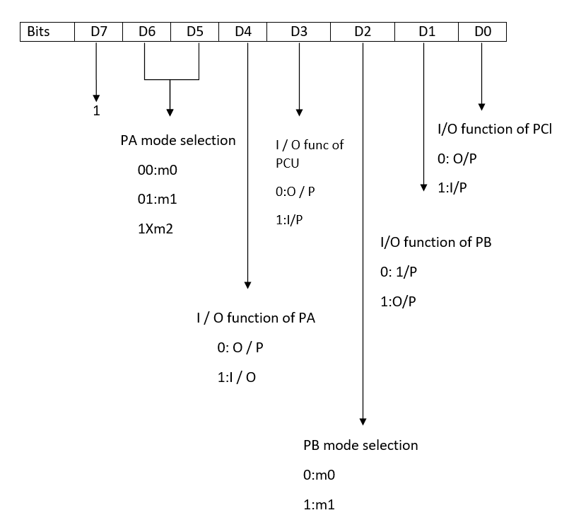
BSR modes use the most significant bit (D7) as 1, while input and output mode uses the most significant bit (D7) as 0.
The D6 and D5 bits are used to set the port A mode.
| D6 | D5 | Mode |
| 0 | 0 | M0 |
| 0 | 0 | M1 |
| 0 | X | M2 |
Now let's discuss other bits in this mode:
D4 bit: The value of D4 tells whether port A is taking Input or displaying the result. If the value is 1, it takes Input. Otherwise, it displays the result.
D3 bit: Port C high bits are used to determine whether an input or output is being taken. If D3 is 1, then port C is taking Input. Otherwise, the output is displayed.
D2 bit: The value of D2 indicates the mode in which port B is operating. If it is zero, then the port is in m0 mode; otherwise, it is in m1 mode.
D1 bit: This field indicates whether port B is taking Input or displaying the result. It should be 1 if it is taking Input. Otherwise, it should be displayed.
D0 bit: Port c lower bits are used to determine whether Input is being taken or output is being displayed. Initially, if D0 is 1, then Input is being taken. Otherwise, the output is displayed.
Resetting the 8255 microprocessor will clear the control word register contents, setting all ports to Input.