ER Diagram for School Management System in DBMS
What is ER Diagram?
An ERD, or entity relationship diagram, is a diagram that depicts the connections between a group of entities contained in a database. In other words, ER diagrams aid in describing a database's logical layout. Entities, Attributes, and Relationships are the three fundamental notions on which ER flowcharts are founded. Rectangles are used to represent entities in an ER diagram, ellipses are used to specify attributes, and diamonds are used to show relationships.
At first glance, an ER diagram looks a lot like a flowchart. However, the ER diagram contains many special symbols with meanings that make this model unique. The motive of an ER diagram is to symbolize the Entity Framework infrastructure.
Components of ER Diagram
- Entity: An entity may be an item, a class, a person, or a place. In an ER diagram, the entities can be depicted as rectangles.
- Entity set: It is an entity type but defined at some point B. such as On the first day of classes, students signed up. Other examples:
A customer purchased a vehicle currently registered in Florida last month. A related term is an instance where a particular person or car is an instance of an entity set.

Entities are classified into two types –
• Strong Entity Sets
• Weak Entity Sets Strong Entity Sets
Strong Entity set
An entity type that consists of key attributes or has enough attributes to form a primary key attribute is called a strong entity set. Represented by a single rectangle.
for example: - student role number, Employee's EmpID
Weak entity set
An entity does not have a primary key attribute and depends on another strong entity via a foreign key attribute. Represented by a double rectangle.
Let's take an organization as an example. A manager, product, employee, department, etc., can be considered a unit.
Attributes:
An entity's characteristics are described by its attributes. It utilizes Ellipse to render properties.
Examples of student qualities include ID, age, contact information, name, etc. Key feature of attributes are as follows:
- The primary properties of an entity are represented by its key attributes, represents the primary key, while ellipses that indicate key properties are underlined.
Composite Property
Compound attributes are qualities that are made up of numerous other attributes. Ellipses are used to express composite qualities, and these ellipses are related to other ellipses.
Multi-valued characteristics
Multiple values are possible for attributes. Multivalued attributes are what these attributes are known as. Multivalued qualities are represented by double ellipses. A student might have several phone numbers, for instance.
Derived attributes
A derived attribute is one that can be created from another attribute. A dashed ellipse might be used to symbolise it.
For instance, an individual's age can be deduced from another feature, such as date of birth, and changes through time.
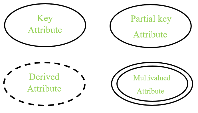
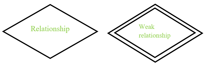
- Relationship
Relationships are used to describe relationships between entities. A rhombus is used to represent relationships. Think of relationships as verbs. For example, a designated student can enroll in a course. The two entities are the student and the course, and the relationship depicted is the enrollment act thus it connects the two entities. Relations are typically displayed as diamonds or labels directly on the connection lines.
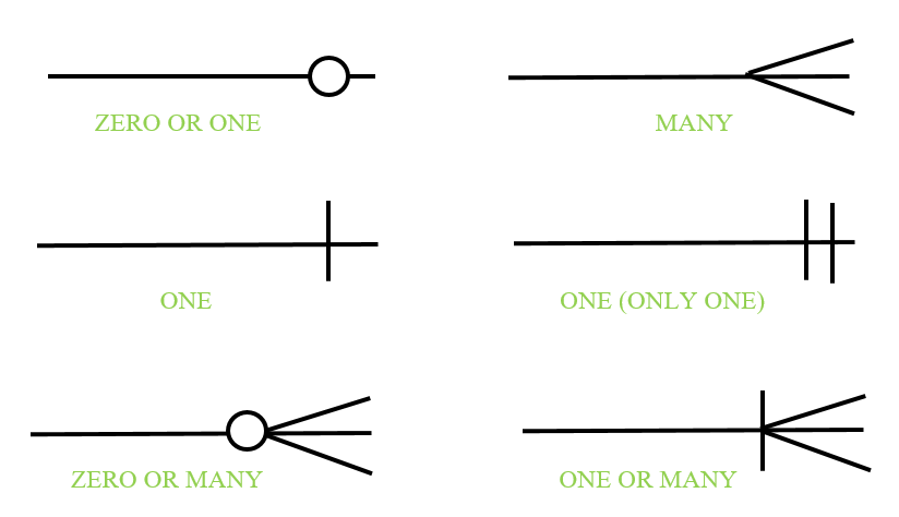
Cardinality
Defines numeric attributes for relationships between two entities or entity sets. Relationships are used to describe relationships between entities. A rhombus is used to represent relationships.
The types of relationships are:
- One-to-one relationship
When only one instance of an entity is associated with a relationship, it is said to be a one-to-one relationship.
For example, a woman can marry a man and a man can marry a woman.One-to-many relationship
When there is only one instance of the left entity and multiple instances of the right entity are associated with the relationship, it is called a one-to-many relationship.
For example, a scientist can invent many inventions, but the inventions are only made by certain scientists.
- Many-to-many relationshi
When multiple instances of a left entity and multiple instances of a right entity are associated with a relationship, it is called a many-to-many relationship.
- For example, a collaborator can be assigned many projects and a project can have many collaborators.
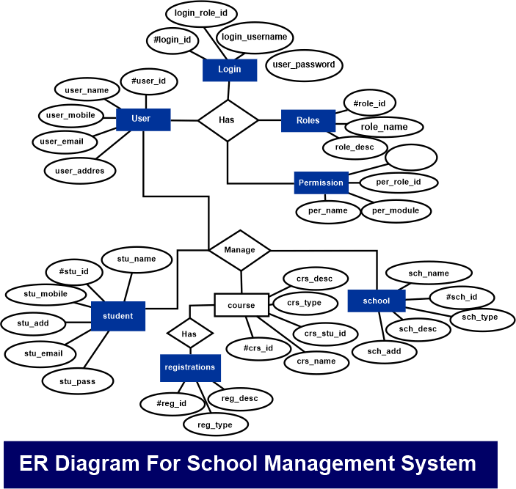
ER Diagram for School Management System
The ER diagram of the school management system shows the relationships of the system's entities that form the database design. It represents the logical structure of a system's database or data storage. For this purpose, the entities of the school management process, their properties, and the interactions between them are identified.
The school management system database design is outlined using an ER (Entity Relationship) diagram. This sketch is the fundamental basis for the data storage of the system acting as the destination and source of the data.
A look back at ER models
To establish a standardized convention that may be utilized as a conceptual modeling tool, Peter Chen created ER Diagrams in 1971. Many models were offered and considered, but they needed to be more appropriate. Charles Bachman's data structure diagrams also influenced his idea.
ER Diagram for School Management System
What is a school management system?
A school management system is a platform of software that helps schools run smoothly by digitizing and automating many academic and administrative tasks.
A school management system facilitates the flow of information for schools that need to keep thousands of important and confidential data safe. Students can easily update and access their information online with proper database management.
Functions of the school management system
- School Management: School management is the main function of this system, and the ER diagram contains the basic details of the school. This basic information consists of courses and programs offered.
- Student Management: This feature plays a big role in the system as it collects important information about students. This information is used to track transactions and other important matters related to the system.
- Course and Subject Management: School administrators must determine the courses selected for each student and assign appropriate instructors to the subjects covered by each course.
- Instructor Management: This system manages instructor information, complete schedules, and all the information needed to manage instructors.
- Appointments: This feature saves transactions made by students and teachers. This includes information and timetables for each subject and timetable.
Explanation of ER diagram of the school management system
The database design of this school management system is based on school requirements management. The system can encrypt student information.
School administrators can access information about student status and important transactions. It can handle student and faculty files and data needed to manage transactions made by enrollees.
Entities in the school management system and their characteristics
1. School entity: The attributes of a school are its name, type, id, and description.
2. Student entity: Student name, student id, student mobile, student college id, student email, student password, student address, and student username are all attributes of the student entity.
3. Class entity: Class attributes include the following: class id, class student id, class description, class name, class type, and classroom.
4. The instructor entity's attributes include the teacher's id, name, address, email, mobile number, password, username, and college identification.
5. Course entity: The course's attributes include the student id, course id, registration, description, name, year, and kind of course.
6. Registration entity-attributes of registration include student identification, registration identification, registration number, registration of courses, registration name, registration type, registration description, and registration date.
School-Based Database Description
1. School details are stored in the School table or all tables
2. Entity types (enrollment, school, student, class, course) have a primary key and a unique key.
3. The Class and Course entities are foreign key bound to the School, Student entities.
4. There are one-to-one and one-to-many relationships between schools, students, courses, enrollments, and classes.
5. All Schools, Students, Courses, Enrollments, and Classes of an entity are normalized to reduce duplicate records.
6 Implemented indexing of each table in school management system for query execution.