ER Diagram for Company Database in DBMS
What is ER Diagram?
An ER diagram (short for Entity Relationship Diagram), also known as an ERD, is a diagram that shows the relationships of a set of entities stored in a database. In other words, ER diagrams help to explain the logical structure of a database. ER flowcharts are based on three basic concepts: entities, attributes, and relationships. It contains various symbols such as rectangles to represent entities, ellipses to define attributes, and diamonds to represent relationships.
At first glance, an ER diagram looks a lot like a flowchart. However, ER diagrams contain many special symbols, the importance of which makes this model unique. The purpose of ER diagrams is to represent the Entity Framework infrastructure.
Components of ER Diagram
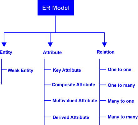
Entity:
An entity may be an item, a class, a person, or a place. In an ER diagram, the entities can be depicted as rectangles.
Entity set: It is an entity type but defined at some point. Such as, Students enrolled in classes on the first day. Other examples: -
A customer purchased a vehicle currently registered in Florida last month.
A related term is an instance where a particular person or car is an instance of a related entity set.

Entities are classified as strong, weak, or related.
- A strong entity can only be defined by its attributes, while a weak entity cannot.
- A related entity links an entity (or elements) within an entity set.
- References attribute uniquely defines an entity within an entity set.
- The entity key can be Super, Candidate, or Primary.
- Super Key: - A set of attributes (one or more) that together define an entity within an entity set.
- Candidate key: - This is an extra minimal key. This means the fewest number of attributes that can act as super keys. An entity set can contain multiple candidate keys.
- Primary Key: - A candidate key chosen by the database designer to uniquely identify the entity set. Take an organization for example. Entities can be managers, products, employees, departments, and so on.
Attributes
Attributes describe the properties of an entity. Render attributes using Eclipse.
Descriptive attributes: - A property or property of a relationship (as opposed to an entity).
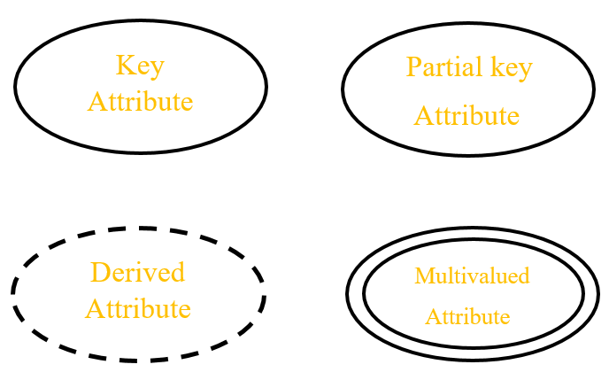
Attribute Category:
Attributes are classified as simple attributes, compound attributes, derived attributes, single-valued attributes, or multivalued attributes.
This means that the attribute value is atomic and cannot be further decomposed.
Composition:
Sub-attributes are derived from attributes.
Derivation:
Attributes are computed or derived from other attributes,
Multiple attribute:
values are specified. Multiple phone numbers per person.
Single value:
Just an attribute value. You can combine types like this:
A simple single-valued attribute or a complex multivalued attribute.
For example, ID, Age, Contact, Name, etc. are student attributes.
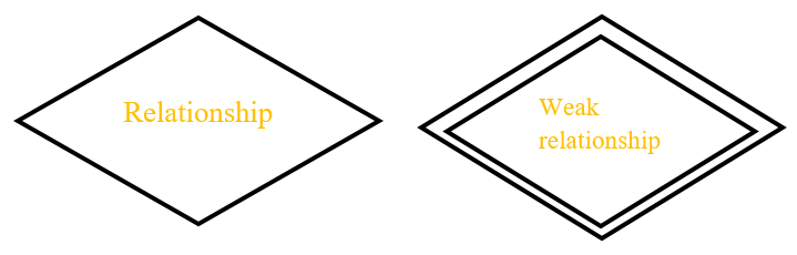
Relationship
Relationships are used to describe relationships between entities.
A rhombus or rhombus is used to represent relationships. Think of relationships as verbs. For example, a designated student can enroll in a course. The two entities are Student and Course, and the relationship represented is Enrollment Behavior. Thus he unites the two beings. Relations are usually displayed directly on the connection line as diamonds or labels.
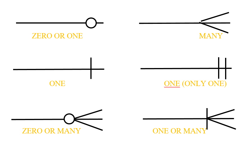
Cardinality
Defines numeric attributes for relationships between two entities or entity sets. The three principal cardinal relationships are one by one, one by several, and several by several. A one-to-one example is a student associated with a mailing address.
One-to-many (many-to-one depending on the direction of the relationship) example: - A student enrolls in multiple courses, but all of those courses have one connection to that student.
Many-to-many example: - A pupil as a collection is related to more than one college members, and a college member is related to more than one students.
Cardinality view:
Cardinality can be viewed as look-across or same-side, depending on where the symbol appears.
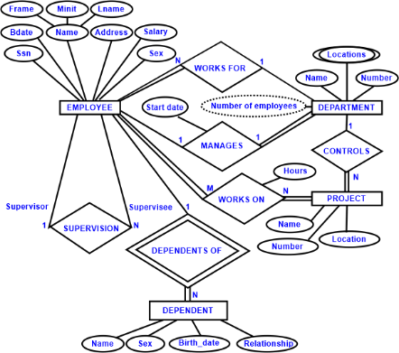
ER Diagram for Company Database
- ER Model stands for Entity Relationship Model. This is a high-level data model. This model is used to define the data elements and relationships of a particular system.
- It helps to develop database concepts. It also creates a data view that is very simple and easy to design.
- In ER Modeling, database structures are represented as entity-relationship diagrams. Such as, Corporate Database.
Company Database Description
- A company is organized into departments.
- Each department has a unique name and number and is headed by a specific employee.
- Track this employee's start date. We started leading the department.
- Departments can have multiple locations.
- Departments manage multiple projects with unique names, numbers, and locations.
- Store each employee's name, social security number, address, salary, gender, and date of birth.
- Employees are assigned to departments but work on some non-essential projects managed by the same department.
- Track hours per Week on which employees work on all projects.
- Also track each line manager-employee.
- Want to track everyone's family Clerk for insurance purposes.
- Retains name, gender, date of birth, and all family members
Entities and Attributes
Entities that are "things" in the real world.
Independent existence.
– Physically existing objects – Specific people, cars,
homes, or employee
- Objects with conceptual existence - companies, jobs, or
university courses.
Each entity has specific properties called attributes
– The employee's name can describe an employee's attribute.
Such as, Age, address...
Attribute Type
- Composite attributes can be decomposed into smaller subparts representing more basic attributes' independent meanings.
- Indivisible attributes are called atomic attributes.
- Most attributes have a unique value for a specific entity. It is said that such attributes have a unique value.
- In some cases, attributes can have values in the following ranges. In the same entity, such attributes are said to be multivalued.
- There are instances where two (or more) attributes are associated.
- Certain entities may not have values applicable to certain entities.
In such case, you can also use null if you don't know the value of attributes of a particular entity.
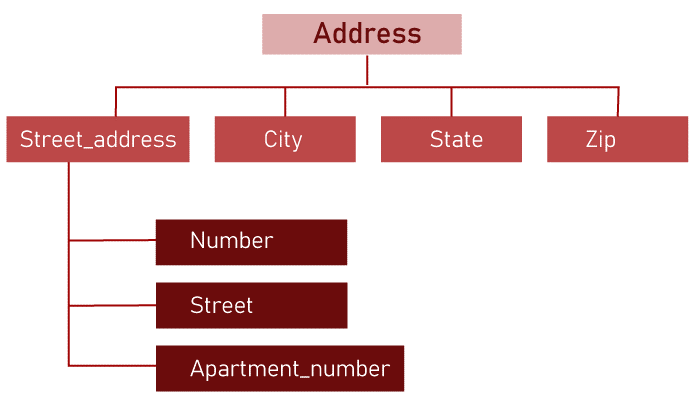
A HIERARCHY OF COMPOSITE ATTRIBUTES
Entity type
- An entity type defines a set of identical entities. Such as Employees and Company.
- Entity types describe schema or intent
- Individual entities are specific entity types.
Set of values
Value set (or domain) specifies the value set that can be assigned to attribute
– The value set for the age attribute of EMPLOYEE is 16
up to age 70
•Sets of values are not shown in ER diagrams.
Original concept design for Company database
Attribute Name, Number, Locations, Manager, and Manager Start Date.
Here, Location is the only multivalued attribute.
- You can specify that each name and number is a key attribute because each is specified as unique.
- Entity type DEPENDENT with attribute Employee, Dependent's name, gender, date of birth, relationship (e.g., employee).
- attribute name, number, location, and control. Everyone by name and number is the important attribute.
- Attributes Name, SSN, Gender, address, salary, date of birth, affiliation, at a glance. Both name and address can be combined attribute.
- Need to go back to users and check if there are any users to do this, then refer to individual components of a name --
First Name, Middle Initial, Last Name - or street address.
Pre-designing entity types
Department
name, number, {location}, manager, Manager Start Date
Business
name, number, city, administrative department
Employee
Name (First name, Middle name, Last name), Social Security Number, Gender, Address,
Salary
date of birth, department, manager, {Works On(Project, Hours)}
Relationship
Relationship type and relationship instance:
A relationship type R between n entity types (E1, E2, ..., En)
Define a set of associations between these entities type.
R is the set of relation instances RI.
Each RI associates n entities (e1, e2, ..., eN), each
The entity, EJ in RI, is a member of entity type EJ, 1 ≤ j
Degree of relationship type
- Each entity type E1, E2, ...En is Join relationship type R and equal for each of the individual entities e1,e2,..en is to join the relationship instance R1=(e1, e2,..., de)
- Degree of relationship type is a number of the participating entity type.
- Twice the relationship type is called Binary, one of degree 3, is called ternary.
Role name and Recursion relationship
- The role name indicates the role. Participating entities play with all relationships.
- If all entity types are different, the role name is unnecessary.
- May involve the same entity type different multiple times in relationship type roll.
Relationship type restrictions
Cardinality ratio
– Indicates the number of relationship instances. Companies can participate
Participation restrictions
– indicates whether the entity's existence depends on the entity about his relationship with other companies' relationship type
Structural restrictions
– Cardinality Ratio + Participation Conditions
Cardinality ratio
- The ratio of Department: Employee is 1:N.
- The ratio of employee: Project is M: N (WORK_ON)
- The ratio of employee: Division is 1:1 (management)
Participation limit
Total– If all employees must work in the department EMPLOYEE entity in WORKS_FOR is called Total. Sometimes called existence dependence.
Partial– Part of "part" of the group is the employee company
connected to the department entity through MANAGES, not necessarily at all.
Relationship attributes
The number of hours the employee spends in a Week working on a project
1: attribute or 1: 1 - You can specify N relationship types migrated to one of the participating entity types
– MANAGES start date is transferable employee or department
N relations must be attributes determined by a combination of participation entity
Weak entity type
Entity types without key attributes are called Weak entity type
Entities with an entity type of Week are identified as follows.
A specific entity of another entity type identification relationship
Weak entity types always have a total participation limit
Speech information processing system, LIS, NTU ER-33
Structural constraints
- Includes setting structural constraints of matching pairs of integers (min, max)
- Whenever legal entity E joins a relation r.
- 0<=minimum<=maximum, maximum>=1
- Each unit e of E is at least minimum and maximum relation instances in R
- min=0 means partial participation
- min>0 means full participation
Structural ER Diagram