3D command in AutoCAD
Below is a list of commonly used AutoCAD commands that are used when working with 3D solids.
- POLYLINE (PL) – You may generate a 2D polyline with the POLYLINE (PL) command. It is essential to close a polyline when attempting to create a form while using the Solid Model Tools. If a polyline is not closed, a mesh object will be produced. The Solid Model Tools do not identify mesh objects.
Creates a 2D polyline, a single object that is made up of line and arc segments.
The segments of the PLINE command are joined, which sets it apart from the LINE command. The LINE command treats each section as a separate item. All line segments are treated as one object when using PLINE.
To Draw a Polyline
- Click PLINE.
- Indicate the first point of the polyline.
- Indicate the endpoint of the first segment.
- Continue to add segments as required. Polylines are made up either straight lines or arcs. By changing the command line option, you may switch between Line and Arc.
- Press Enter to end the command, or choose Close Shape to close the polyline to its original start point.
- EXTRUDE (EXT) – The EXTRUDE command is used to convert a 2D object into a 3D object. The original 2D object is deleted from the drawing when the EXTRUDE command is used.
Consider the below image:
The Extrude command is widely used to create walls, shapes, etc.
Consider the below 2D surface.
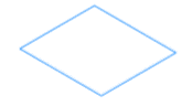
Here, we have developed a rectangle.
- To create a solid of the above figure, follow the below steps:
- from the ribbon panel select Extrude command, as shown below in the image::
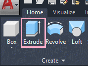
on the command line type Extrude < press Enter.
- Select the object, which you want to Extrude.
- Here, we have selected the rectangle.
- Press Enter.
- Now, specify the height of the Extrude.
- We can specify the height in +Z or –Z direction.
- We can either determine the height with the cursor or by the value.
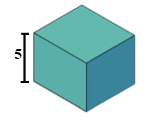
- Here, we have specified the value = 5.
- The object will now look like the below image:
- To create a surface of the 2D rectangle, follow the below steps:
- On the command line type Extrude < press Enter.
- On the command line Type Mode or M < press Enter.
- On the command line type Surface or SU < press Enter.
- Select the object to Extrude.
Here, we have selected the rectangle. - Press Enter.
- Specify the height of the Extrude.
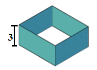
Here, we have specified the value = 3.
The object will now look like the below image:
- To Create using Direction/ path/ Taper Angle/ Expression, follow the below steps:
- On the command line type Extrude < press Enter.
- Select the object, which we want to Extrude.
- Select one option from Direction/ path/ Taper Angle/Expression.
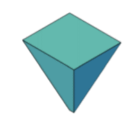
Here, we have selected Taper Angle. - Press Enter.
The figure will now appear as:
Example 2:
Consider the 2D object shown below:
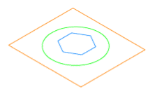
Here, we have drawn three objects.
The steps are listed below:
- On the command line type Extrude < press Enter.
- Select the object.
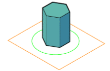
Here, we will first select the inner polygon. - Press Enter.
- Specify the height. Here, we have entered height = 4.
The object will appear as:
- Again, on the command line type Extrude < press Enter.
- Select the object.
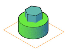
Here, we will select the circle. - Press Enter.
- Specify the height. Here, we have entered height = 5.
The object will appear as:
- Again, Type Extrude on the command line < press Enter.
- Select the object.
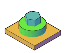
- Here, we will select the outer rectangle.
- Press Enter.
- Specify the height. Here, we have entered height = 1.
The object in 3D will now look like the below image:
Similarly, we can create different objects, models, etc. with the help of the Extrude command.
- PRESSPULL (PRESS) – The PRESSPULL command converts a 2D object to a 3D object or extends a 3D surface. When the PRESSPULL command is used with a 2D object, the 2D item remains in the drawing.
In AutoCAD 3D, the Presspull command is used to generate an area defined by a closed border.
Or
It is used to pull a border that is contained.
It may also be used to generate a 3D solid in the instance of a circle or the inside of a confined region.
Objects like arc can be utilised to build a 3D surface.
The Presspull command may also be used to extract a portion of an item. For instance, making holes, etc.
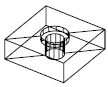
Consider the below image:
Let's understand by example.
Example 1:
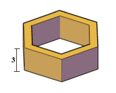
Consider the below 2D surface.
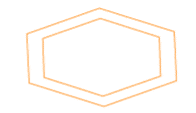
Here, we will extrude the boundary of the hexagon.
The steps are listed below:
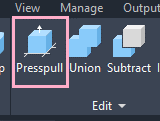
1. Select the Presspull icon from the ribbon panel, as shown below:
Or
Type PRESSPULL on the command line and < press Enter.
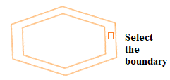
2. Select the object or bounded area.
Here, we will select the bounded area between two edges of hexagon, as shown below:
3. Specify the Extrusion height.
Here, we have specified height= 3.
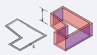
The object will now look like the below image:
To remove a part of an object,
- Use the Presspull command < select the area to be removed < pull that selected area in outer direction < press Enter.
Let's understand with an example.
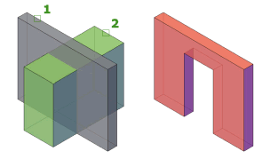
Example 2:
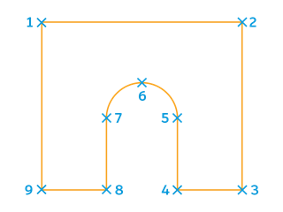
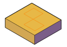
Consider the below 2D surface.

Here, we will remove two small rectangles from a big rectangle.
The steps are listed below:
1. from the ribbon panel select the Presspull icon, as shown below:
Or
Type PRESSPULL on the command line and < press the Enter button.
2. Select the object or bounded area. Here, we will select the rectangle (object).
3. Specify the Extrusion height. Here, we have specified height= -2.
It is because we want to extrude in -Z direction.
The object will now look like the below image:
We can also specify in +Z direction.
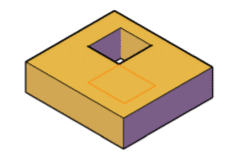
4. Select the small rectangle and extend downward < click anywhere on the screen.
It will now look like the below image:
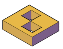
5. Select another small rectangle and again extend downward < click anywhere on the screen.
The object will now appear as:
- BOX – The BOX command will allow you to create a 3D box by selecting 3 points in the X, Y, and Z axes.
- 3DMOVE (3M) – The 3DMOVE command will allow you to move an object in either the X, Y, or Z-axis.
In a 3D view, displays the 3D Move gizmo to aid in moving 3D objects a specified distance in a specified direction.

With the 3D Move gizmo, you can move selected objects and subobjects freely or constrain the movement to an axis or plane.
When you choose an item in a view with a 3D visual style and the default gizmo (DEFAULTGIZMO) is 3D Move, the 3D Move gizmo is displayed. If the visual style is set to 2D Wireframe, the command transforms the visual style to 3D Wireframe.
By default, the 3D Move gizmo is displayed in the middle of the chosen 3D object or objects. The 3D Move Gizmo shortcut menu allows you to align, move, or switch to another gizmo.
You may, for example, use the Align Gizmo With Object option on the shortcut menu to align the 3D Move gizmo with the plane of a face or object. The move operation's direction is then restricted in relation to this work plane.
The following prompts are displayed.
Select objects: Selects the 3D objects you want to move. When you have selected the objects, press Enter.When you have selected an object, the gizmo is displayed. You can constrain the movement by clicking one of the following locations on the gizmo:
- Move along an axis. Click an axis to constrain the movement to that axis.
- Move along a plane. Click the area between the axes to constrain the movement to that plane.
Stretch point
When you are specifying the move using the gizmo, sets the new location of the selected objects. Drag and click to move the objects dynamically.
Copy
When you are specifying the move using the gizmo, creates a copy of the selected objects instead of moving them. You can make multiple copies by continuing to specify locations.
Base point
Specifies the base point of the 3D objects you want to move.
- Second point. Specifies where the 3D object or objects will be dragged. You can also move the cursor to indicate a direction and then enter a distance.
Displacement
Specifies a relative distance and direction for the placement of the selected 3D objects using coordinate values that you enter at the command prompt.
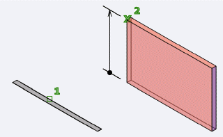
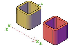
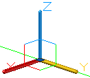
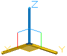
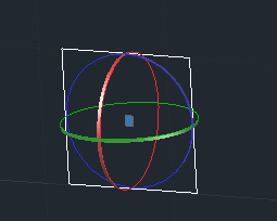
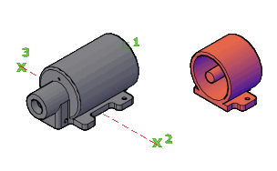
- 3DROTATE (3R) – The 3DROTATE command will allow you to rotate an object about the X, Y, or Z axes.
This command aids in the rotation of 3D objects. Rotating objects will be far more important in 3D than in 2D. We will now be working in three dimensions, which means we will have three planes on which to place the front face of the item we are making.
You may simply rotate an object from the plane x,y to x,z or y,z in AutoCAD by using the 3DROTATE command.
Notice on the image above how we rotated a copy of the primary surface on the left.
How to 3D-rotate an object in AutoCAD
- Select the object to 3D-rotate
- type 3DROTATE and press ENTER
- Specify the base point of rotation
- Pick a rotation axis
- Specify the angle of rotation
- 3DPOLYLINE (3DPOLY) – The 3DPOLYLINE command will allow you to create a polyline with points that can exist in the X, Y, and Z axes.
- UNION (UNI) – The UNION command will allow you to join separate 3D objects into one.
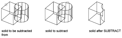
- SUBTRACT (SU) – The SUBTRACT command will allow you to subtract 3D objects from another 3D object.
Creates as a new object by subtracting one overlapping region or 3D solid from another.

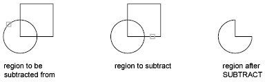
You can make a 3D solid using SUBTRACT by removing one set of existing 3D solids from another, overlapping set. A 2D region object can be created by removing one set of existing region objects from another, overlapping set.
It is not suggested to use SUBTRACT with 3D surfaces. Instead, use the SURFTRIM command.
Pick the things you wish to keep, hit Enter, and then select the ones you want to remove.
Objects in the second selection set are subtracted from objects in the first selection set. A single new 3D solid or surface is created.
When subtracting regions, objects in the second selection set are subtracted from objects in the first selection set, and a single new region is created.
You cannot use SUBTRACT with mesh objects. However, if you select a mesh object, you will be prompted to convert it to a 3D solid or surface.
The following prompts are displayed.
Select objects (to subtract from)
Specifies the 3D solids, surfaces, or regions to be modified by subtraction.
Select objects (to subtract)
Specifies the 3D solids, surfaces, or regions to subtract.
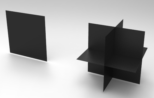
- SLICE (SL) – The SLICE command will allow you to create a joint through a 3D solid.
Creates new 3D solids and surfaces by slicing, or dividing, existing objects.

The cutting plane is defined with 2 or 3 points by specifying a major plane of the UCS, or by selecting a planar or a surface object (but not a mesh). One or both sides of the sliced objects can be retained.
- 3D solid objects can be sliced using specified planes and surface objects
- Surface objects can be sliced by specified planes only
- Meshes cannot directly be sliced or used as slicing surfaces
Sliced objects retain the layer and color properties of the original objects, however the resulting solid or surface objects do not retain a history of the original objects.
The following prompts are displayed.
Objects to slice
Specifies the 3D solid or surface object that you want to slice. If you select a mesh object, you can choose to convert it to a 3D solid or surface before completing the slice operation.
- Start point of slicing plane
- Planar object
- Surface
- Z axis
- View
- XY
- YZ
- XZ
- 3points
Start point of slicing plane
Sets the first of two points that specify the slicing plane's orientation. With this option, the slicing plane is always perpendicular to the current UCS's XY plane. After specifying the second point on the plane, you can either keep both sides of the sliced object or specify another point on the plane's side that you want to keep.
Second point on plane. Sets the second of two points on the slicing plane. If the second point is not located on the XY plane of the UCS, it is projected onto the plane.
- Specify a point on the desired side to keep
- Keep both sides
Planar object
Aligns the cutting plane with a plane that contains the selected circle, ellipse, circular or elliptical arc, 2D spline, 2D polyline, or planar 3D polyline.
- Select a circle, ellipse, arc, 2D-spline, or 2D-polyline. Specifies the planar object that defines the cutting plane. A planar 3D polyline object can also be selected.
- Specify a point on desired side to keep
- Keep both sides
Surface
Aligns the cutting plane with a selected surface.
- Select a surface. Specifies a cutting surface.
Note: You cannot specify mesh, 3D face, or thickened objects as the cutting surface.- Select the sliced object on the desired side to keep
- Keep both sides
Z axis
Defines the cutting plane by specifying a point on the plane and another point on the Z axis (normal) of the plane.
- Specify a point on the section plane. Sets a point on the slicing plane.
- Specify a point on the Z-axis (normal) of the plane. Specifies a point that defines the axis that is perpendicular to the slicing plane.
- Specify a point on the desired side to keep
- Keep both sides
View
Aligns the cutting plane parallel to the current viewport's viewing plane. Specifying a point defines the location of the cutting plane.
- Specify a point on the current view plane. Sets a point on the object to start the slice.
- Specify a point on the desired side to keep
- Keep both sides
XY
Aligns the cutting plane with the XY plane of the current UCS. Specify a point to define the location of the cutting plane.
- Point on the XY-plane. Aligns the cutting plane parallel to the XY plane of the UCS and passing through a specified point.
- Specify a point on the desired side to keep
- Keep both sides
YZ
Aligns the cutting plane with the XY plane of the current UCS. Specify a point to define the location of the cutting plane.
- Point on the YZ-plane. Aligns the cutting plane parallel to the YZ plane of the UCS and passing through a specified point.
- Specify a point on the desired side to keep
- Keep both sides
XZ
Aligns the cutting plane with the XZ plane of the current UCS. Specify a point to define the location of the cutting plane.
- Point on the XZ-plane. Aligns the cutting plane parallel to the XZ plane of the UCS and passing through a specified point.
- Specify a point on the desired side to keep
- Keep both sides
3points
Defines the cutting plane using three points.
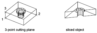
Specify a point on the desired side to keep
Uses a point to determine which side of the sliced object to keep. The point cannot lie on the cutting plane.
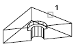
Keep both sides
Retains both sides of the sliced objects.