AutoCAD Draw commands
We may use the Draw commands to make new objects like lines and circles. The majority of AutoCAD drawings are made up of only these fundamental elements. To get the most out of AutoCAD, you need to know how to utilize the Draw commands.
The commands accessible on the Draw toolbar will be reviewed in the following areas.
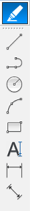
Draw Toolbar
Line Command
You may use the line command to make a succession of continuous line segments. Each segment is a distinct line object that may be modified.

Optional Commands
You will have the following choices available when using the line command:
Close — Once you've drawn two or more lines, the close option will appear. The command "c" creates a closed shaped from the current point of the line back to the beginning point.
Undo — In the command line, type "u" to undo the previous line drawn.
Ortho mode — Ortho mode impairs your ability to draw straight lines. When ortho mode is turned on, you can only draw lines along the UCS axis. If you turn off ortho mode, you'll be able to draw lines at any angle. The F8 key may be used to turn ortho mode on and off. The command line will inform you if ortho mode is activated or not after you push the button.
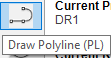
Command for a Polyline
You may use the polyline command to make a single object out of a series of segments. You can make straight-line, arc, or a mix of the two parts. Unlike line command segments, each polyline must be altered as a whole.
Optional Commands
The following options will be available when using the polyline command:
Arc — Using the arc option, you may construct an arc section for your polyline. Additional information on drawing arcs may be found in the Draw Arc (a) section.
Close — Once you've drawn two or more lines, the close option will appear. Using the command line, type "c" to produce a closed form from the current position of the line back to the beginning point.
Half width – The half width option determines how wide the following polyline section will be. Widths larger than zero result in broad lines that will fill automatically.
Length – Even if you're starting a new polyline command, the length option draws a line segment of a given length at the same angle as the preceding line segment. The new line segment is drawn tangent to the previous arc segment if the preceding section was an arc. If you select the length option, you will be asked for the line's length.
Undo – In the command line, type "u" to undo the previous line segment drawn.
Width – The width option determines how wide the next polyline section you draw will be. Widths larger than zero result in broad lines that will fill automatically.
Ortho mode – Ortho mode impairs your ability to draw straight lines. When ortho mode is turned on, you can only draw lines along the UCS axis. If you turn off ortho mode, you'll be able to draw lines at any angle. The F8 key may be used to turn ortho mode on and off. The command line will inform you if ortho mode is activated or not after you push the button.
Circle Command
A circular entity will be created by using the circle command.

Optional Commands
Before selecting the first point using the circle command, you will have the following alternatives.
3P — The three-point option allows you to choose three locations on the circle's circumference.
2P — The two-point option allows you to choose two ends of the circle's circumference.
Ttr (tangent, tangent radius) – The Ttr option forms a circle tangent to two objects with a defined radius. You'll choose three points, the first of which will be an item for the circle's initial tangent. A circle, arc, or line must be the chosen object. The circle's second tangent is the second point. A circle, arc, or line must be chosen as the starting point. The object's radius can then be specified.
Diameter - If you create a circle using the normal approach, the center of the circle, you'll have the diameter choice for your second point. Instead of entering the radius, type "d" on the command line to indicate the circle's diameter.
Command of the Arc
To make an arc drawing element, use the Arc command. You may make an arc by supplying various point and value combinations. The conventional method for creating an arc is to identify three points: the arc's start points, center, and terminus.
The radius of the arc is determined by the distance between the start point and the center. Although this is the most common technique to make an arc segment, the alternatives allow you to make the arc in a variety of ways.

Optional Commands
Depending on how you draw the arc, you will have a variety of options accessible to you when using the Arc command. If you choose the starting point as your first point, for example, you will have the choice of choosing the center point or the terminus for the following point you select on the screen. Look at the alternatives below to see when they will be available.
It is vital to note that to draw an arc, you will need three points: the first point (1), the second point (2), and the third point (3). Any combination of the beginning point, centre point, and endpoint can be used.
Center-When you initially start the Arc command, the center choice will be offered. This will allow you to select the arc's center point as the starting point (1).
Center/end-if you chose the starting point as the arc's first point, the Center and End options will be accessible (1). To pick the arc's endpoint as the second point, use "E" for End (2). For the second point of the arc, you do not have to put "C" for Center (2). This is the standard setting.
Angle/Chord Length — After you've chosen the centre point as your first point (1) and a second point (2) at each end of the arc, you'll have angle and chord length options. In the command line, type "A" for angle and then the angle dimension. Enter "L" for chord length to specify the chord's length. The chord length is the distance between the start and end points of an arc.
Angle/Direction/Radius - If you chose the start point (1) and endpoint (2) as the arc's initial two points, the final set of options will be accessible. To insert an angle dimension between the start and finish points, type "A." To enter Direction, type "D."
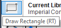
Command Rectangle
This command creates a rectangular polyline by enabling you to pick the rectangle's two opposite corners. You may also choose the type of corners (fillet, chamfer, or square).
Optional Commands
The following options will be available when using the polyline command:
Chamfer/Elevation/Fillet/Thickness/Width
Area/Dimensions/Rotation- After you have picked the first corner of the rectangle, you will be able to choose from the following options.
Command in Text
A single-line text object is created with the Text command. You may use single-line text to make one or more lines of text, each of which is a separate object that you can move, reformat, and change.

Optional Commands
Before selecting your first point with the text command, you will have the following options:
Justify/Style
Command for Linear Dimensions
You may use the Linear Dimension command to generate a horizontal or vertical dimension. You may also dimension an object in the drawing by selecting it.

Optional Commands
Before selecting your first point with the linear dimension command, you will have the following options:
Select Object — Rather than picking points to construct a dimension, you may select an object and a dimension will be produced for that item automatically.
Mtext/Test/Angle/Horizontal/Vertical/Rotated – After you have chosen two points for the dimension, you will have the following alternatives.
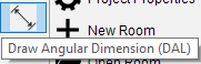
Command for Angular Dimensions
You may build a dimension at an angle with the Angular Dimension command. Unlike the Linear Dimension command, this will produce a dimension parallel to the two points in the picture. You may also dimension an object in the drawing by selecting it.
Optional Commands
Before selecting your first point with the linear dimension command, you will have the following options:
Select Object — Rather than picking points to construct a dimension, you may select an object and a dimension will be produced for that item automatically.
Mtext/Text/Angle (Mtext/Text/Angle) – After you have chosen two points for the dimension, you will have the following alternatives.