Sweep Command in AutoCAD
We'll utilize the SWEEP command here, which, like the EXTRUDE function we used when we produced our first figure in AutoCAD, helps us get cylinders out of circles and can do a lot more.
When compared to the EXTRUDE command, the SWEEP command has a few distinctions. It aids in the creation of 3D objects from 2D objects by simply defining the path that the 2D item will take to SWEEP to produce the 3D object.
AutoCAD is a computer-aided 2D and 3D design programme that uses a variety of fun instructions. Sweep is one of the software's commands. We may build a solid form using the sweep command by assigning any 2d shape to a certain route.
We will learn how to handle sweep command parameters in Auto Cad programme and comprehend the sweep command through an example in this post. The Sweep command is found in the Create menu of this software's home tab. So, let's get started talking about this command in Auto Cad.
Using the sweep command, a 2D sub-object or object is swept along an open or closed path to generate a 3D surface or solid.
An open-ended item is swept to generate merely a 3D surface, whereas an object encompassing the region is swept to make a 3D solid or surface.
Consider the following illustration:
Sweeps a 2D item or subobject along an open or closed route to create a 3D solid or 3D surface.

3D surfaces are created by open-ended items, whereas 3D solids and surfaces are created by things that surround an area.
Use the DELOBJ system variable to destroy the original geometry that was used to generate the object. The DELOBJ system variable is disregarded for associative surfaces, and the source geometry is not erased.
The following prompts will appear.
Sweep able Objects
This property specifies the object that will be used as the sweep profile.
Path Sweep
The sweep route is determined by the item you choose.
Mode
Controls whether a solid or a surface is created by the sweep motion. Depending on the SURFACEMODELINGMODE system variable, surfaces are swept as NURBS or procedural surfaces.
Alignment
Specifies whether the profile is oriented to be normal to the sweep path's tangent direction.
The profile will automatically align if it is not perpendicular (normal) to the tangent of the path's start point. To avoid this, type No at the alignment question.
The starting point
Sets the starting point for the sweeping objects.
Scale
A scale factor for a sweep operation is specified. The scale factor is applied consistently to all items swept from the beginning to the conclusion of the sweep path.
- Reference. The selected items are scaled based on the length you specify by choosing points or entering numbers.
Twist
Sets the twist angle for the swept items. The twist angle determines the amount of rotation along the sweep path's full length.
- Bank. Indicates whether the swept curve(s) will naturally bank (rotate) along a 3D sweep path (3D polyline, spline, or helix).
The following are examples of paths and objects that may be swept to generate a 3D object:
- Arcs
- Solid
- Polylines
- Lines
- Splines
- Elliptical Arc is a kind of elliptical arc.
- Regions
- Sub-objects at the edges
- Trace
By holding down the Ctrl key, we may pick the sub-objects.
Let's have a look at an example.
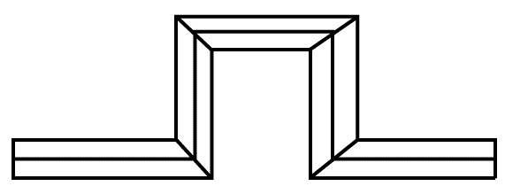
Consider the 2D object below:
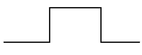
Join the lines or use the Polyline command to create the object.
The steps are as follows:
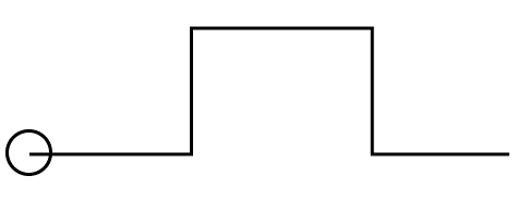
1. Draw a circle at the object's terminus, as seen below:
2. From the ribbon panel, choose Sweep icon as shown below:
Or
On the command line or at the command prompt, type SWEEP and hit Enter.
3. Sweep the thing you want to sweep. We'll choose a little circle here.
4. Hit the Enter key.
5. Choose a sweep route. We'll pick the object we made using the polyline here.
6. Hit the Enter key.
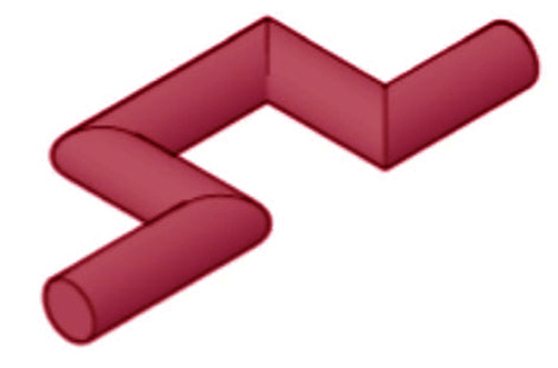
7. As indicated below, the sweep will be created:
8. Switch the Visual control to Conceptual and the View control to SW Isometric.
The item will now resemble the image below:
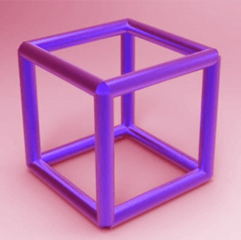
Similarly, the SWEEP command may be used to construct a large number of 3D objects.
Building a 3D spring in AutoCAD using the SWEEP and HELIX commands is a simple way to show the SWEEP command's capabilities.
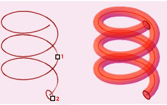
Changing from the things in Image 1 to the ones in Image 2.
1st image
2nd Image

Let's take use of this chance to learn how to make an AutoCAD Helix.
In AutoCAD, make a helix.
1. Press ENTER after typing HELIX.
2, Determine the base's central point.
3. Enter a number for the base radius.
4. Enter a number for the top radius.
5. Determine the helix's height.
It's worth noting that there are several choices available when using the HELIX command. You may create a helix depending on the number of turns and/or the height difference between two successive turns with this command.
Here are some examples of what you can do with the HELIX command.
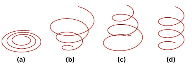
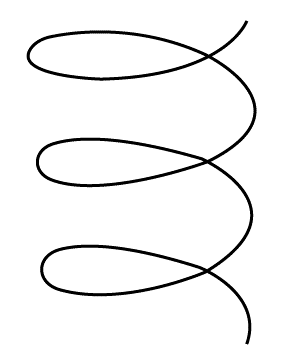
(a) Spiral
(b) Smaller base radius than top radius (spring)
(c) The base radius is greater than the top radius (spring)
(d) a consistent spring
The end result is this picture.

In AutoCAD, to utilize the SWEEP command
- Press ENTER after typing SWEEP.
- Select the sweepable object and click ENTER.
- Choose the SWEEP route.
It's that simple.
Step 1:
Step 2: Now we need to create a circle and repeat it so that we have a total of 12 circles.
Step 3: Sweep 12 times, using a circle as the sweep object and a segment as the sweep route each time.
The end result is this picture.