AutoCAD 3d Drawing
3D CAD software is a type of computer-aided design software.
Three-dimensional computer-aided design, or 3D CAD, is a technique for design and technical documentation that automates the drawing process. 3D CAD software is used by architects, engineers, and other professionals to precisely model and display things on a computer using a collection of points in three dimensions. Autodesk offers a wide range of 3D CAD tools to enable users explore and exchange ideas, visualise concepts, and test how creations will operate before they are built.
Workflow for 3D Modeling and Drawing
The following is an example of a common procedure for making 3D models in AutoCAD using 3D drawing:
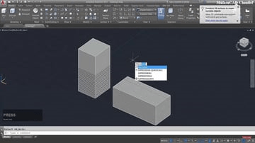
- Create a new drawing using a 3D template like "acad3d.dwt."
- Select "3D Modeling" as the workspace.
- To make the 3D form, use the drawing tools in your 3D modelling programme.
- All of the drawing tools are the same in both 2D and 3D workspaces, with the exception of 3D Polyline, which is only available in the 3D configuration. You may use this tool to make polylines, which are linked segments that might be non-coplanar. To put it another way, you can make your polyline on many work surfaces at the same time.
- To make your model, use the modelling tools in the 3D Modeling workspace. In AutoCAD, you may use a variety of advanced 3D modelling commands. Here are a few of the more frequent ones:
- Press pull allows you to choose a closed drawing object such as a wall outline and give it height.
- Extrude operates similarly to Press pull, only you enter a number value instead moving your mouse.
- Sweep lets you to build a solid shape by extending a drawing shape or profile along a given route. This command will be used to build a freeform shape in the lesson below.
- Union is a technique for combining various objects, surfaces, or areas into a single entity.
- Subtract lets you make a solid by subtracting one from the other.
- Include material information in your model to obtain information about your item, such as weight and density. Render your model to make it appear more realistic (optional).(Optional) To bring your model to life, send it for 3D printing or CNC machining.
With the foregoing in mind, 3D drafting is only a phase in the AutoCAD process of building a 3D model.
AutoCAD 3D Commands: An Overview
AutoCAD is a three-dimensional CAD programme that is widely used in the business world. Autodesk created it in the year 1982.
AutoCAD 360 is a mobile and online programme that is touted as an alternative to AutoCAD. AutoCAD has a unique collection of commands and operations for both 3D and 2D modelling and drawing, as well as an incredible number of tools.
The third Z coordinate is crucial in 3D. When working in 2D, the user is primarily concerned with the X and Y axes, and coordinates are rarely employed. When dealing with 3D, on the other hand, the user makes use of all of the coordinates, which may make their job much easier.
Requirement of 3D model
Today's technology allows us to bring our imaginations closer to reality through 3D modelling, printing, rendering, and other methods. There is a plethora of software available on the market that allows customers to turn their ideas into reality. Some of the software is free, while others has a cost.
People are becoming more drawn to technology that allows them to produce and create vibrant designs with each update and new discovery. The use of 3D is an unavoidable component of the design process.
Without it, the design resembles a rough drawing. Furthermore, 3D is a boon to all interior designers and architects, as it allows them to create life-like models of any structure, office, or exterior, as well as interiors such as furniture, walls, display pieces, and more.
Modeling in three dimensions
3D modelling is the process of creating a mathematical representation of any surface of an item in three dimensions using particular software. A three-dimensional model can even be rendered as a two-dimensional image using the 3D rendering approach.
3D printers may also be used to physically generate 3D models. To build 3D models, a variety of applications is utilized, including AutoCAD, MAX, MAYA, and others.
3D models are also in great demand among game creators. Sprites are pre-rendered graphics of 3D models that are used in some computer games. This allows the designer to see the model from all angles and ensure that the product made is identical to the original.
Currently, 3D models are employed in the film business as objects in both animated and real-life images. Furthermore, because 3D models, renders, and effects are extensively employed in movies and the gaming business, they are the most commonly used VFX. Organ 3D models are also used in the medical field.
The following are some of the advantages of 3D modelling: –
- Users may get a more evocative design and even see virtual pictures of their projects by using 3D models.
- A 3D model of architecture is far more intriguing and realistic than a 2D one.
- A user's experience with a 3D model is far more intriguing and rewarding than with a 2D picture.
- The impact of all minor and major changes made to a 3D model can be seen by the user. This also helps to improve the quality of the designs without losing time or money.
- Interior designers benefit greatly from 3D models since they may construct and change 3D interior and exterior designs to their liking.
- A 3D design allows the user to see the physical size of the items as well as their distance from other things in the layout. This function is quite useful for seeing and modifying object configurations based on their sizes.
- For the finest results, some artists combine 3D modelling with 2D computer-rendered graphics from the 3D model.
The Most Important AutoCAD 3D Commands
Let's have look at the most important commands:
- Revolve is found in the Draw > Modeling > Revolve menu. This AutoCAD 3D function rotates a 2D object around an axis to generate a 3D solid.
- Extrude: Extrude may be found under the Draw > Modeling > Extrude menu.
This AutoCAD 3D Extrude function allows the user to extrude a 2D face along a line or route to produce a 3D object. A cylinder, for example, may be made by choosing a 2D circle and extruding it along a route. - Sweep : Location of Sweep: Draw > Modeling > Sweep
This command allows the user to extrude 2D objects without having the 2D face be perpendicular to the path's starting. - Union Modify > Solids Editing > Union is where you'll find it.
This AutoCAD 3D function allows you to merge two objects into a single entity. - Subtract
Location of Subtract: Modify > Solids Editing > Subtract
This command is the polar opposite of the union command; it works when both objects have a shared region. The item A is then subtracted from the object B using this command. - Intersect
Modify > Solid Editing > Intersect is where you'll find it.
The user is left with the region that is shared by both objects after using this AutoCAD 3D command.
3D Drawing Software
AutoCAD is generally used to create two-dimensional drawings. While 3D objects may be created, AutoCAD is designed on a flat, sketch-based interface. AutoCAD has a large number of pre-defined 3D objects. Cylinders, spheres, wedges, and a variety of other things are among them. Users, on the other hand, utilize 2D objects and change them using 3D instructions. Users employ AutoCAD 3D functions such as Extrude, Sweep, Revolve, and Union.
If the user is working with 3D models, they should also be aware of the usefulness of the Viewport function. The viewport command divides the drawing area into numerous windows, allowing various views of the model to be projected. These include the object's top, front, and left/right perspectives.
Conclusion – 3D Commands in AutoCAD
For novices, AutoCAD 3D Commands is a lengthy and difficult programme. Nonetheless, it is incredibly handy and has several advantages.
It is a strong computer-aided design (CAD) programme for architectural and mechanical engineering. It includes one of the most comprehensive toolboxes and functions for 2D drawing. However, when it comes to 3D design, it stands out because to its 3D rendering capability, which produces spectacular and colorful results.
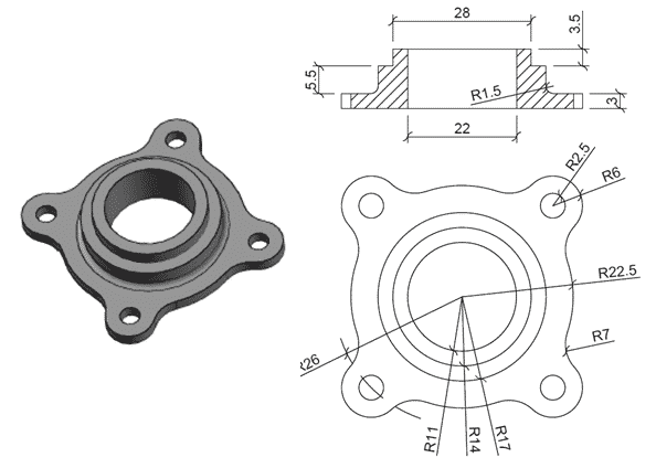
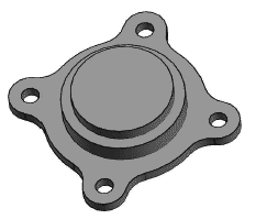
A 3D practice drawing instruction in AutoCAD.
Here's the 3D model of the object, as well as its 2D sketch, which we'll learn to model in this post. For this sketch, I recommend switching to the drafting and annotation workspace; you can also obtain CAD files for this instruction here.
AutoCAD 2D and 3D practice drawings are related.
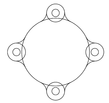
- Using the CIRCLE command from the home tab's draw panel, make sure the circle with radius 2.5 units has its Center on the perimeter of the circle with radius 26 units.
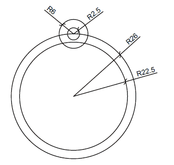
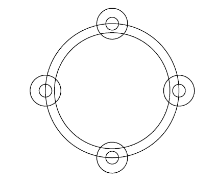
- Select Polar Array from the Home tab's Modify panel, then two little circles at the top of the geometry. Now set the array's Center to the largest circle's Center, and enter 4 in the Number of Items field.
You'll be given an array similar to the one in the image below.
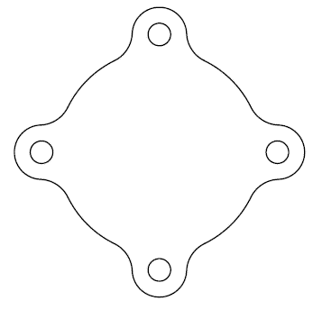
- Delete the largest circle and use the FILLET command to create a fillet radius of 7. Enter R on the command line and input 7 as the fillet radius.
Now, as illustrated in the image below, apply this fillet to the circle's intersections with R2.5 and R22.5.
- To make it seem like the one below, trim all of the geometries.
- Hit enter after typing J on the command line, then pick full geometry and press enter again.
All external 2D segments will be combined into a single unit.
It's possible that you'll have to use the JOIN command a few times to entirely join the geometry.
- On the Visualization tab, in the Views and Visual Styles section, change the view to southwest isometric and change the visual style to shaded.
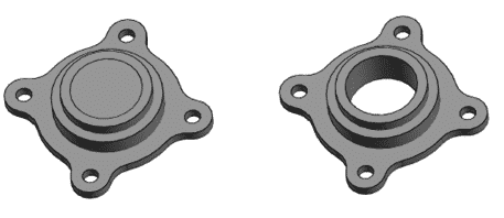
- At the command line, type PRESSPULL and click anywhere in the geometry. Click inside the geometry, not the geometry. On the command line, type a height of 3 units and click Enter.
- Create an R17 circle on top of the object you produced in the previous step, but make sure Dynamic UCS is switched on before you do so. Select the circle command, drag the mouse to the top layer, click the center of the geometry in the center of the circle, enter a radius of 17 units, and press Enter again to enable the dynamic UCS. On the command line, type EXT and hit Enter.
- Then, in the previous step, choose the circle you created and click Enter once more. To end the extrude command, enter a height of 5.5 units and hit Enter again.
- Create a new 14-unit-radius circle with the same center point as the previous step's geometry and extrude 3.5 units as previously.
- Now write UNION and hit ENTER, then choose entire geometry and hit ENTER again to verify that all geometries are united into a single unit.
- Create an R11 circle on the geometry's topmost surface.
Now, on the command line, write PRESSPULL and press Enter, then click inside the 11-unit-radius circle and enter -12 as the depth of geometry; this will create a hole in the existing geometry.
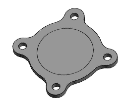
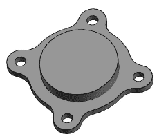
- To begin the fillet command, type F and hit enter on the command line, then type R and enter a radius of 1.5 units for the fillet. Select the edge between the flat piece and the biggest cylinder, as seen in the figure below, and then press enter twice to exit the command.
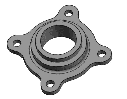
The final geometry will resemble the illustration displayed above.