Chamfer Command in AutoCAD
Introduction
AutoCAD is a computer-aided 2D and 3D design programme that is used by many designers. This application has a number of commands that will assist us in completing our objective.
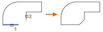
The chamfer command in Auto Cad programme is one of the commands that makes our work simpler. The chamfer command allows you to clip the corners of two adjacent sides of any two-dimensional form at any distance or angle by specifying precise values.
Beveled or chamfered edges are the edges of two 2D objects or the adjoining faces of 3D solid.

A bevel, often known as a chamfer, is a kind of chamfer.
- an angled line that connects two straight 2D objects at their ends
- a 3D solid's sloping transition between two surfaces or neighboring faces.
In the sequence in which the items are selected, the given distances and angles are applied.
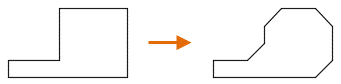
Make a chamfer in two dimensions.
Choose two objects of the same or different object categories to define a bevel or chamfer: lines, polylines, rays, and xlines.
The line defined is formed on the same layer as the two selected objects if they are on the same layer. If not, the line will be drawn on the current layer. The color and line type of an item are affected by the layer.
When making a 2D chamfer, the following instructions appear.
First Line
Select the first of two objects or the first line segment of a 2D polyline to determine the chamfer.

To apply a corner, use the second line or shift-select.
Choose the second item or line segment of a 2D polyline to determine the chamfer.
Hold down the Shift key when selecting the second item or line segment of a 2D polyline to expand or trim the selected items for a clean corner. The current chamfer distance and angle settings are given a temporary value of zero while Shift is kept down. If the selected objects are straight line segments of a 2D polyline, they might be close together or separated by another segment. When a segment divides the chosen segments from one another, the segment that separates them is deleted and replaced with a chamfer.
When a chamfer or bevel is applied to a hatch border that was previously established using separate items, hatch associativity is lost. Associativity is preserved if the hatch border is specified by a polyline.
Undo
Reverses the command's previous action.
Polyline
A chamfer line is placed at each vertex of a 2D polyline where two straight line segments meet. The chamfer lines create new polyline segments unless the Trim option is set to No Trim.
The chamfer distance is not accommodated by line segments that are too short.
Distance
Sets the chamfer distance and XY angle from the intersection point of the chosen items to the first item or line segment.
If both values are set to zero, the specified objects or line segments are enlarged or trimmed such that they intersect.
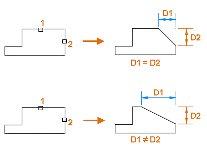
Sets the chamfer distance and XY angle from the first item or line segment from the intersection point of the chosen objects.
The selected objects or line segments are expanded or trimmed such that they intersect if both values are set to zero.
Trim
Controls whether or not the chosen objects are clipped to meet the chamfer line's ends.
- Trimming. Selected objects or line segments are trimmed to match the chamfer line's ends. Sets the chamfer distance and XY angle from the intersection point of the chosen items to the first item or line segment.
- If both values are set to zero, the specified objects or line segments are enlarged or trimmed such that they intersect.
The current value of the TRIMMODE system variable is saved.
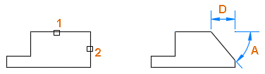
Method
The method for calculating the chamfer line from the intersection point of the specified objects or line segments is controlled.
- Distance. Two distances define the chamfer line.
- Angle. A distance and an angle define a chamfer line.
CHAMMODE is a system variable that stores the current value.
Multiple
Allows for the beveling of many objects at the same time.
Make a three-dimensional chamfer (Not available in AutoCAD LT)
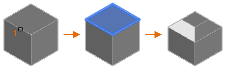
A chamfer can be applied to the edge of a 3D solid or surface. When defining a chamfer, use the edge of a 3D solid or surface as the initial line.
Note: If you choose a mesh object, you may continue the process by converting it to a 3D solid or surface.
After picking the edge of a 3D solid or surface, the following questions appear.
Option to Select a Surface
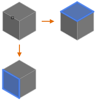
You may designate which nearby surface is the base surface after selecting the edge of a 3D solid or surface. The base surface is what determines which edges can be chamfered.
- Next, the nearby surface is selected and set as the base surface.
- OK, that's it (Current). Accepts the chosen surface as the starting point.
After selecting the base surface, you must define the two chamfer distances as well as the chamfering of the base surface's edges.
Distance between chamfers
Sets the base and other (adjacent) surface chamfer distances.
Expression
A mathematical equation is used to control the chamfer distance.
See About Controlling Geometry with the Parameters Manager for a list of operators and functions that can be utilised.
Edge
Chamfer the edges of the base surface that you want to chamfer. To end the selection, press Enter.
Loop
In a sequential tangent edge selection mode, you can choose all edges that correspond to the base surface.
When a 3D solid box's side is selected as the basis surface, all tangential edges on that side are selected.
Use the Edge option to return to choosing particular edges that belong to the base surface.