
Offset Command in AutoCAD
The offset command is employed to form parallel lines, concentric circles, and parallel curves in AUTOCAD.
We can offset any object through a point or at a specified distance. We can create as many parallel lines and curves with the help of the offset command in AUTOCAD. We can make many copies of the line at a particular distance in a short time by using the offset command in AutoCAD. The offset command is working as a copy command for lines. But for circles, rectangles, arcs, or any polyline objects, it is not working as the copy command like it works for line. It will copy a circle or any object at a selected distance but as per the proportion from the centre.
We can invoke this command. from the modify panel in the Home tab of AUTOCAD. Or we are able to type ‘O’ (AutoCAD offset shortcut key) in the command bar and press the Enter key to offset an object.
By invoking the Offset command, it will ask for ‘specify offset distance’, it’s important to specify the distance in this command.
Give distance as per the requirement at which you wish to make copies.
Then it will ask ‘select object to offset’. Select the object of which you want a replica to be made.
After that, it will ask ‘select point on side to this command. Click on anywhere on which side you want a duplicate of the object to be made. It will make another copy of this command.
To make another copy, it is not necessary to try and do the whole process. Just select the previous copied offset and again select it at any side.
To make multiple this command at anyone particular side, select ‘multiple’ from the command bar at the time of selecting one point at anyone’s side as shown. And just click on that side.
EXAMPLE OF AUTOCAD OFFSET:
1.LINE (AUTOCAD OFFSET):
For example, I would like to draw staircase lines and I want to use this command to draw parallel lines.
In addition, select this command from the modify panel in the home tab. Or type ‘O’ in the command bar and press the Enter key.
Then give dimension. For example, 300mm.
After that, select the first drawn line and click on one side.
However, I will select a previous parallel copied line and will select ‘multiple’ from the command bar.
Then I will only click on one side. It will make parallel copies automatically.
2.CIRCLE (AUTOCAD OFFSET):
For example, I need to make some concentric circles on the inner side of the first circle.
The process is almost the same as above. Select the inner side of this command.
We can also offset polyline objects the same as the circle using this command.
3.ARC OFFSET:
For example, I need to draw parallel curves.
In addition, the process is the same as above.
EXAMPLE 1:The object to offset is shown within the below image:
The steps are listed below:
1.Create an object with two lines and an arc, as shown above.
2.Join the object. To offset the whole figure, we need to join the segments of that figure. It will be joined as a polyline.
The steps to join the object are listed below:
1.Type J or join on the command line.
2.Select objects or multiple objects to join. Here, we will select the two lines and an arc.
3.Press Enter.
3.Select the Offset icon from the ribbon panel.
Or
Type O or offset on the command line or command prompt and press Enter.
4.Specify the value of offset distance. For example, 1.
5.Press Enter.
6.Select the object to offset. We need to select the object with a small square cursor.
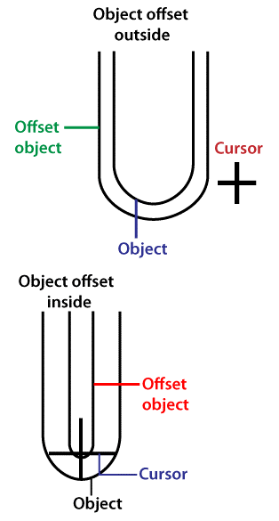
7.Move the cursor inside or outside to place the offset object, as shown in the below image:
8.Press Esc or Enter to exit from the offset command.
The distance between the object and the offset object is 1, as mentioned in step 4.
EXAMPLE 2: To remove the object after the offset.
We can also remove the object after the offset. The object is shown in the below image:
The steps for such an example are listed below:
1.Create an object using the polyline command, as shown in above image. We can also create it using line command and can join them using Join
2.Select the Offset icon from the ribbon panel.
Or
Type O or offset on the command line or command prompt and press Enter.
3.Type E or erase on the command line and press Enter.
Type yes to erase the source object after offsetting.
Or
Click on the yes button on the command line, as shown in the below image:
4.Specify the value of offset distance. For example, 1.
5.Press Enter.
6.Select the object to offset with a small square cursor.
7.Move the cursor in the particular direction and click on that point.
Press Enter.
8.Press Esc or Enter to exit from the offset command.
EXAMPLE 3.
1.Create a circle with any specified radius. For example, 3.
2.Select the Offset icon on the ribbon panel.
Or Type O or offset on the command line or command prompt and press Enter.
3.Specify the value of offset distance. It is the distance value to create a concentric circle from the original circle. For example, 1.
Press Enter.
4.Select the object to offset. We need to select the object with a small square cursor.
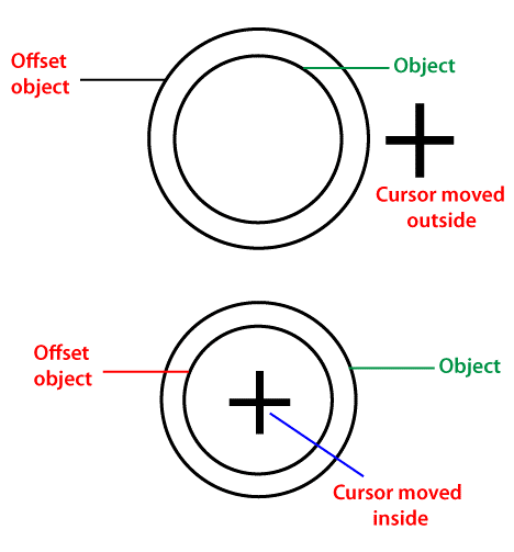
5.Move the cursor inside or outside to place the offset object, as shown in the below image:
6.Press Esc or Enter to exit from the offset command.
Multiple Offset
The multiple offset command in AutoCAD is used to apply the offset multiple number of times.
Let's understand it with an example.
The steps are listed below:
1.Select the line command from the ribbon panel and create a line of dimension 4. We can draw any object according to the requirements.
2.Type O or offset on the command line and press Enter.
3.Specify the offset distance. For example, 1.
4.Select the object to offset.
5.Type M or multiple on the command line and press Enter.
6.Continue clicking in the corresponding direction to place the offset objects.
AUTOCAD offset setting:
Now, the question is can we fillet or chamfer the perimeter of the offset object?
So, the solution is yes, we are able to do this by using the offset system variable. Do this setting:
The current setting is, Erase source=No, Layer=Source, OFFSETGAPTYPE=0
By changing this ‘OFFSETGAPTYPE’ system variable setting we can fillet the perimeter.
Type ‘OFFSETGAPTYPE’ within the command bar and press Enter key.
Give 0,1, or 2 numbers as per requirement and then press Enter key.
System variable numbers:
0 = Extend line segments at a sharp corners or edges to their projected intersections.
1 = It Fillets line segments. And the radius of the line equals the offset distance which you have been given.
2 = It chamfers line segments. And the perpendicular distance from each chamfer to the corresponding vertex is same or equal to the offset distance.
COMMON FAQs RELATED TO OFFSET:
1.What is the use of the offset command in AutoCAD software?
The offset command is used for forming parallel lines, concentric circles, and parallel curves. We can offset (Make a replica) of any object at a specified point or at a certain distance. We can form as many parallel lines and curves by using the offset command.
2.Why is AutoCAD offset distance is not working?
So, the solution is firstly checking your Unit setting and Dimension settings. It should be the same as earlier.
And secondly, the Unit setting and offset distance are you entering is the exactly same or not. For example, the unit set is in meters or mm and you are giving offset distance in inches or feet that is in other units.
In this case, the offset command distance will fail to work. So, In conclusion, both should be the exactly the same
3.Where is the offset command in AutoCAD software?
The offset command is placed at the ‘Modify’ panel in the ‘Home’ tab of the software. Or we can type ‘OF’ in the command bar and press Enter to invoke the offset command.
4.What you fail to create from the command offset?
We can create many replicas of the line at a specified distance in a short time by using the offset command in AutoCAD.
The offset command is working as a copy command for lines. But in case of circles, rectangles, arcs, and any polyline objects offset are not working as a copy command.
It will copy a circle or any object at a certain distance but according to the proportion from the center of the circle.
5.Why can’t I offset a polyline in AutoCAD software?
Please assure first that the polyline doesn’t have zero-length segments, i.e., each vertex pair is connected with a non-zero length segment.
If there is a zero-length segment, firstly right-click and click on the properties from the option. Then change the current vertex from zero in the geometry.