
×

Ellipse command in AutoCAD

Two focal points are encircled by a curve, which is known as the Ellipse.

Two of the ellipse's axes, which specify its length and breadth, determine its form.

The Ellipse command on the AutoCAD display allows you to construct ellipses in general. By putting the start and end points on two different axes, we may make an ellipse.

Depending on the specification, the first and second axes of the ellipse might be classified as either minor or major axes.

The icon of Ellipse will look like the below image:

 Ellipse command in AutoCAD 

Move the pointer of your mouse on the Ellipse icon to view the dialogue box for Ellipse in AutoCAD. It will look like the given image:
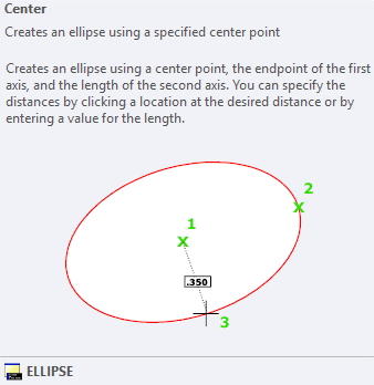
 Ellipse command in AutoCAD 

It consists of the drop-down list, which includes other options such as Elliptical Arc, Center, and Axis. The list will look like the given image:
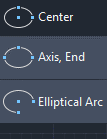
 Ellipse command in AutoCAD 

Let's discuss each type of Ellipse in detail.

CENTRE

In this procedure, the length determines the second axis while the centre point and terminus define the first axis. To make such an ellipse, we can either choose a point or a distance value.

Let's use an illustration to clarify.

The actions are detailed below:

1.As seen in the figure below, click the Ellipse symbol on the ribbon panel, and then select Center from the Ellipse's drop-down list:
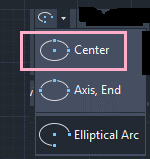
 Ellipse command in AutoCAD 

Or

On the command line or command prompt, type el or ellipse and hit Enter.

Fill up the command line using C or copy.

Enter the key.

2.On the viewport, specify the Ellipse's centre.

3.Declare the first axis' terminus like in the illustration below:
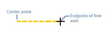
 Ellipse command in AutoCAD 

Either the point or the distance value can be specified. The first axis's centre and terminus will be used to determine the distance,such as 3.

As seen in the graphic below, we may alternatively pick the vertical axis as the initial axis:
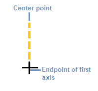
 Ellipse command in AutoCAD 

4.Enter  key.

5.Set the second axis' endpoint or distance value.For example, 4.

6.Press Enter.

7.The Ellipse will be formed, as seen in the illustration below:
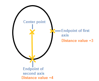
 Ellipse command in AutoCAD 

If the vertical axis was chosen as the first axis, the ellipse so formed is shown in the below image:
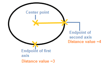
 Ellipse command in AutoCAD 

The three points are defined in a manner similar to above to create the ellipse.

It is displayed below:
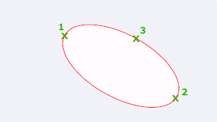
 Ellipse command in AutoCAD 

The first axis' position and length are determined by the points 1 and 2, whereas the second axis' distance between its centre and terminus is determined by the point 3.

Elliptical Arc

An elliptical arc may be made with the Elliptical Arc command.

For instance:

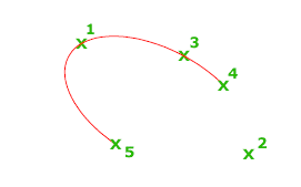
Consider the below image:
 Ellipse command in AutoCAD 

The location and length of the first axis is specified by the points 1 and 2, while the distance between the center and the endpoint of the second axis is specified by the point 3.

The fourth and fifth specified points are the start and end angles.

Let's use an illustration to clarify:

The actions are detailed below:

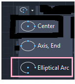
1.Select Elliptical Arc from the drop-down list of the Ellipse by clicking on the Ellipse symbol on the ribbon panel as shown in the illustration below.
 Ellipse command in AutoCAD 

Or

On the command line or command prompt, type el or ellipse and hit Enter.

On the command line or command prompt, type A or arc and hit Enter.

2.Indicate the elliptical arc's terminus or centre.

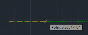
3.As seen below, specify the axis' endpoint:
 Ellipse command in AutoCAD 

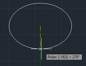
4.As seen below, specify the other axis' endpoint:
 Ellipse command in AutoCAD 

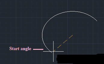
5.Name the starting angle. 30 is an example. The following picture illustrates it:
 Ellipse command in AutoCAD 

6.Indicate the final angle. for instance, 120.

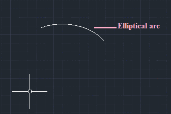
7.The created elliptical arc is shown in the below image:
 Ellipse command in AutoCAD 

We can also specify the Parameter angle instead of the normal angle.

Let's use an illustration to clarify:

Parameter

The vector equation shown below is used to generate the arc for the given angle values:

p(angle) is equal to c + a * cos(angle) + b * sin (angle)

Where,

negative major and minor axis lengths, a and b

central point of the ellipse

Draw an Isometric Circle

If you are drawing on isometric planes to simulate 3D, you can use ellipses to represent isometric circles viewed from an oblique angle.

  • Click Tools menu - Drafting Settings.
  • In the Drafting Settings dialog box, Snap and Grid tab, under Snap Type and Style, click Isometric Snap. Click OK.
  • Click Home tab - Draw panel - Ellipse drop-down - Axis, End.  
 Ellipse command in AutoCAD 
  • Enter i (Isocircle).
  • Specify the center of the circle.
  • Specify the radius or diameter of the circle.

Draw a True Ellipse Using Endpoints and Distance

  • Click Home tab - Draw panel - Ellipse drop-down - Axis, End.
 Ellipse command in AutoCAD 
  • Specify the first endpoint of the first axis (1).
  • Specify the second endpoint of the first axis (2).
  • Drag the pointing device away from the midpoint, and click to specify a distance (3) for half the length of the second axis.

 Ellipse command in AutoCAD 

Draw an Elliptical Arc Using Start and End Angles

  1. Click Home tab - Draw panel - Ellipse drop-down - -  Elliptical Arc.
 Ellipse command in AutoCAD 
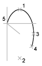
  1. Specify endpoints for the first axis (1 and 2).
  2. Specify a distance to define half the length of the second axis (3).
  3. Specify the start angle (4).
  4. Specify the end angle (5).
    The elliptical arc is drawn counterclockwise between the start point and endpoint.
 Ellipse command in AutoCAD 

Related Topics

AutoCAD 2d Drawing

What is AutoCAD 2D drawing? The act of making and altering technical drawings, as well as annotating designs, is known as 2D drafting and drawing. Drafters create floor plans, construction permit...

3 minutes read.

AutoCAD Drawing

CAD software superior to hand-drawing The user may incorporate accurate measurements in their designs using CAD software. When creating in CAD, it is also much easier to make changes to a...

10 minutes read.

Dim command in AutoCAD

A single command may be used to create many dimensions and dimension kinds. Find You can choose one or more of an item's points to dimension it, and then click to establish...

4 minutes read.

AutoCAD Blocks

cad-blocks.net is a well-organized, contemporary, and easy-to-navigate website where you can download over 5,000 CAD blocks files (dwg files) for use in architectural projects or designs using AutoCAD and other...

6 minutes read.

Wipeout Command in AutoCAD

Use the Wipeout command to conceal some drawing elements without erasing them. It is a background-colored item with concealable edges that have a different hue. To conceal a region in a...

4 minutes read.

Dimension command in AutoCAD

To dimension an item, you can choose one or more of its points, and then click to set the dimension line. When you hover over an item, the DIM command...

8 minutes read.

AutoCAD Software

Computer-aided design software allows you to produce 2-D and 3-D drawings and models instead of using traditional pencil-and-paper drafting to develop designs that can be readily changed. History Autodesk is the company...

5 minutes read.

Lisp command in AutoCAD

Can have AutoCAD automatically load LISP routines Issue: how to have AutoCAD automatically load AutoLISP functions. The program's files must be manually reloaded each time it is run. Solution: You may either utilize the...

4 minutes read.

tcount command in AutoCAD

You can now automatically keep track of the number of blocks and other objects you have in your AutoCAD drawing file thanks to a new feature in AutoCAD 2022 and...

3 minutes read.

Zoom Command in AutoCAD

You may also use the keyboard to access the Zoom command by typing its alias, Z. The Zoom command has numerous possibilities, but the most frequent are Extents, which was...

4 minutes read.

Erase Command in Autocad

In AutoCAD, use the Erase command. In AutoCAD, the Erase command is a highly significant and a valued tool. This command is found in the Modify panel of the home...

3 minutes read.

Mesh Command in AutoCAD

It creates a 3D mesh basic object, such as a wedge, torus, box, cone, cylinder, pyramid, or other shape. Find Mesh primitives, or the fundamental mesh shapes, are comparable to the 3D...

6 minutes read.

Array Command in AutoCAD

AutoCAD's Array Command From the command line, creates duplicates of anything in a pattern. Creates nonassociative, 2D rectangular or polar arrays using historical command line behavior. The copies may take a long...

3 minutes read.

Sweep Command in AutoCAD

We'll utilize the SWEEP command here, which, like the EXTRUDE function we used when we produced our first figure in AutoCAD, helps us get cylinders out of circles and can...

4 minutes read.

Create Block in AutoCAD

Blocks In AutoCAD, the term "blocks" refers to repetitive things that you insert in your designs. Symbols is another name for them. In AutoCAD, the words "Block Library" and "Symbol Library"...

3 minutes read.

Hatch command in AutoCAD

In AutoCAD, the Hatch command is used to fill patterns inside an enclosed region. Hatched, gradient, and solid fill designs are available. A gradient pattern is a seamless transition between two...

5 minutes read.

Overkill Command in AutoCAD

Getting rid of overlapping objects in AutoCAD In the command bar, enter the word OVERKILL.Choose every item you wish to be eliminated of duplicates. To accept the drawing chosen, press enter. Review...

4 minutes read.

Subtract command in AutoCAD

In AutoCAD, use the subtract command. Use the subtract command in AutoCAD. By subtracting one set of existing 3D solids from a second, overlapping set, SUBTRACT may be used to...

3 minutes read.

Chamfer Command in AutoCAD

Introduction AutoCAD is a computer-aided 2D and 3D design programme that is used by many designers. This application has a number of commands that will assist us in completing our objective.The...

4 minutes read.

AutoCAD Electrical software

AutoCAD Electrical report may be a powerful tool however, most CAD users square measure unaware of the way to modify the method of generating reports victimization it AutoCAD Electrical style package...

8 minutes read.