Command list of AutoCAD
Fundamental AutoCAD Commands
Here is a summary of some of the most fundamental AutoCAD commands that every user should be familiar with. These Draw and Modify instructions make up part of the AutoCAD fundamentals, so if you're just learning the programme, you should be familiar with all of these fundamental commands.
L
It may be used to create straightforward lines.
C
It is the AutoCAD command used to create a circle.
PL
You may create a polyline in your drawing by using this command.
REC
In AutoCAD, this command will create a rectangle.
POL
A polygon with a minimum of 3 sides and a maximum of 1024 sides can be created with this command.
ARC
As the name implies, AutoCAD users may create arcs with this command.
Ellipse
The ELLIPSE command can be used to create an ellipse using the main and minor axes, as its name indicates.
REG
To create an area geometry in AutoCAD, use this command.
CO
In AutoCAD, you may copy an object(s) with this command.
ARRAY
You may create a rectangular, polar, or path array with this command.

TR
Trimming a geometry is accomplished with this command.
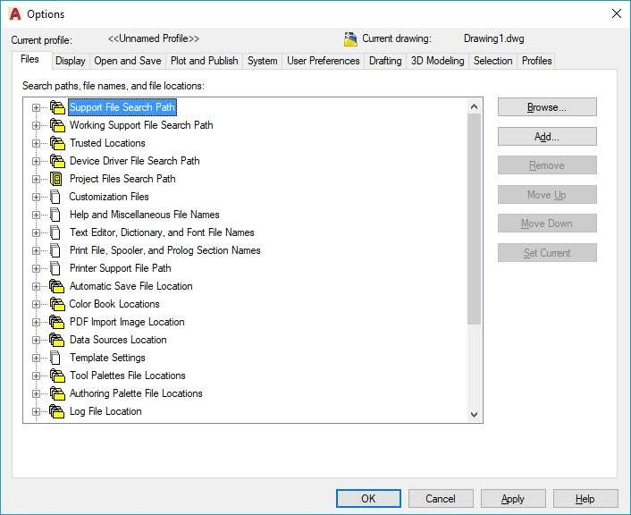
OP
You may access the majority of AutoCAD's settings by using this command to open the options panel.
SC
To alter an object's scale, use this command.
B
This command is used to create a block, and the block definition window may be used to define the block's attributes.
I
Using this command, an existing block or a drawing may be added to AutoCAD as a block.
ST
You may access the text style window, which manages the settings for the default AutoCAD text style, with this command.
X
Using this command, you may convert things like polylines into simple lines, arrays or blocks into simple geometries, etc.
F
With the use of this command, rounded corners, also known as fillets, may be added to the geometry's sharp edges.
CHA
This command may be used to add chamfers, which are slant edges that can be added to sharp corners.
LA
The layer properties manage palette, a tool for adding and managing layers to a drawing, may be opened with this command.
Keys for keyboard shortcuts
The easiest and quickest approach to activate some of the frequent AutoCAD processes or instructions is by using keyboard shortcuts or hotkeys. I've included some of the most popular and practical keyboard shortcuts in this list.
Ctrl + N
To launch a new drawing tab in AutoCAD, use this shortcut.
Ctrl + S
This keyboard shortcut can be used to save a drawing file.
Shift + Ctrl + S
This keyboard shortcut is the "save as" command hotkey and may be used to save the drawing as a new file.
Ctrl + 0
disables palettes and tabs and clears the screen to just display the painting area. To restore the normal AutoCAD interface, press it once again.
Ctrl + 1
To display the properties palette, which shows the item's properties, select an object and press Ctrl + 1. The majority of the object's characteristics may also be altered using this palette. The PR command can also be used to access the property palette.
Related: Boost efficiency by changing AutoCAD's fast attributes
Ctrl + 2
It allows you to access the design center palette, which is filled with a variety of AutoCAD blocks that may be utilized right away in your drawing.
Ctrl + 9
This keyboard shortcut can be used to alter the command line's visibility. Use this keyboard shortcut to reveal your command line if it has accidentally been concealed from view in the drawing area.

Ctrl + C
To copy objects to the clipboard, select the desired items in the drawing area and press Ctrl + C.
Ctrl + V
You may use this keyboard shortcut to paste the copied objects from the clipboard into the drawing while maintaining their original characteristics.
Shift + Ctrl + V
You may use this keyboard shortcut to paste the copied items into a block, which will have a name made up of a random string of letters. By using this keyboard shortcut, you may rapidly construct blocks without opening the create block window.
Ctrl + Z
Use this keyboard shortcut to undo the most recent action you took when painting. You can undo a lot of things by repeatedly pressing this shortcut key.
Ctrl + Y
You may use this keyboard shortcut to undo the most recent action you took.
Shift + Tab
This keyboard shortcut allows you to switch between all of AutoCAD's open drawing tabs.
Status Bar Switch
The status bar is a crucial component of the AutoCAD user interface, and as its tools are commonly used when creating or revising drawings, they are conveniently located there. Status bar icons can be activated or deactivated using keyboard shortcuts, instructions, or simply clicking on the corresponding icon.
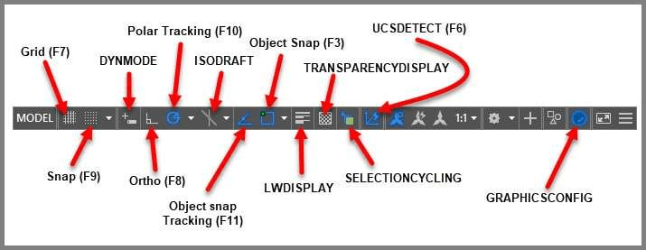
F7
The backdrop grid, which is frequently visible in your drawing area, may be toggled on or off with this status bar tool.
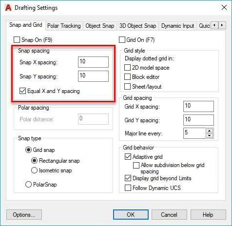
F9
Toggle Snap mode on or off. When Snap mode is activated, the AutoCAD cursor will hop to predefined locations inside the Snap mode-defined drawing area.
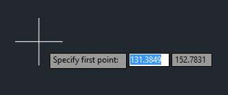
DYNMODE
This system variable's value is set by default to -3, which disables dynamic input; you must adjust it to 3 to enable it. You may dynamically add information to the cursor tooltip by using dynamic input.
F8
Turns on or off Ortho mode. You can only draw lines vertically or horizontally while ortho mode is enabled.
F10
Toggles On/off polar tracking. Lines can be inclined to any angle specified in the polar tracking increment angle while polar tracking is active.
ISODRAFT
In AutoCAD, you may turn on the isometric drawing plane by using this toggle. Isoplane Left, Isoplane Top, and Isoplane Right are your options. Using the F5 function key, you may also switch between different isoplanes. Orthographic is the default setting for the ISODRAFT option.
Find out more about using this tool to create isometric drawings here: AutoCAD isometric drawing techniques
F11
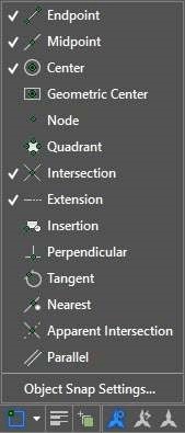
Turns on or off object snap tracking. You may create geometries with their reference by tracking snap points for geometries like centre, midpoint, and endpoint using this option.
F3
The most crucial status bar toggle. This function key toggles the object snap feature on and off, allowing you to precisely snap your cursor to points in the geometry such the End, Center, Quadrant, and Tangent. You may create exact AutoCAD drawings with this feature.
LWDISPLAY
This system variable controls whether line weight is visible in a drawing. If you want to keep the line weight display visible in the drawing area, set this system variable's value to ON rather than its default value of OFF.
TRANSPARENCYDISPLAY
Similar to line weight, this status variable enables you to change an object's transparency and visibility. Transparency may be made visible by setting this system variable's value to 1, or it can be made invisible by setting it to 0.
F6
The function key can be used to turn on or off Dynamic UCS. With dynamic UCS, you may immediately create geometries of a face or another 3D object, regardless of the UCS's position. UCSDETECT system variable, with values of 1 for ON and 0 for OFF, may likewise be used to control dynamic UCS.
GRAPHICSCONFIG
You may launch the Graphics configuration window, which is used to modify settings relating to AutoCAD's display and graphics attributes, using this status bar option. For opening the graphics performance panel, you may alternatively use 3DCONFIG.
General Orders
These are a few commands that may be used regularly in your sketching process to increase productivity. Many of these commands may be recognizable to you, but there are some that you may not be acquainted with and are still mostly underutilized.
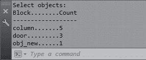
BCOUNT
The number of blocks in your design may be determined with the help of this command. It lists the name of the block and the number of each occurrence that was used in the design. The block must be discernible in the drawing area in order to be counted.
TXTEXP
You can turn single-line and multi-line text into geometry with this command.
XLINE (XL)
You may create an endless number of lines starting from the point of selection by using this command. This infinite line becomes a straightforward line geometry when it is cut or divided into discrete lengths.
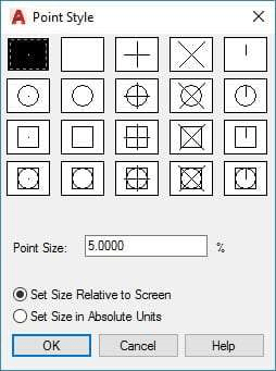
POINT (PO)
This command creates a drawing using a single point geometry. You can use the PTYPE command and choose the appropriate point type from the Point Style box to change the kind of point that was generated by this command.
REVCLOUD
You may create a revision cloud geometry with this command by drawing it by hand.
SKETCH
With the use of this command, you may draw something by hand. To create this freehand sketch, choose Line, Polyline, or Spline as the object type.
MULTIPLE
Use MULTIPLE command to issue the same command more than once without using the Enter key. Press the ESC key to stop the instruction from repeating.
NCOPY
You can transfer nested objects from a block or Xref without blowing them up by using this command.
‘CAL
Even in the middle of a command, you may do computations right on the AutoCAD command line by using this subcommand. While executing any other command, you can start this subcommand by typing 'CAL (don't forget to put an apostrophe before CAL).
Refer to the relevant article for further information on this subcommand.

Related: How to be more productive with AutoCAD in six easy steps
BURST
explodes the attribute-containing block while keeping the setting and layer definition of the attributes. This is very useful if you want to keep the attribute text after the block explodes.
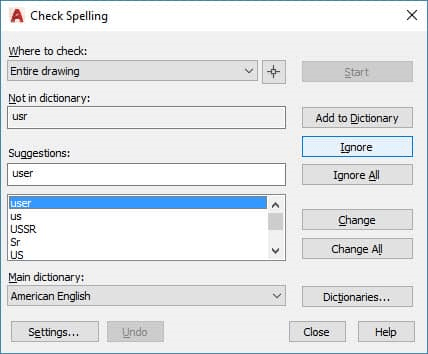
SP
By using this command, you may use the Examine Spelling window to check the spelling of any chosen text and make any necessary corrections.
ARCTEXT
AutoCAD's ARCTEXT command may be used to write text that is arc aligned. Even text that is aligned to a circle can be written with this command. You may read this linked article for more information on this command.
Related: How to curve text in AutoCAD, along Arc and Circle
OOPS
You can use this command to bring back the last drawing object that was removed. If you made several modifications to the drawing after removing an object and then recognised that you would need to restore the deleted object, just write OOPS and hit Enter.
CHSPACE
Using this command, you may switch an object's space from model space to paper space and vice versa. For more information, see the animated graphic below.
DIVIDE
Any 2D shape may be divided into several equal portions with this command. A point geometry will be added to the 2D curve at each point of division. You may read this linked article for more information on this command.
Cut up AutoCAD objects into equal pieces.
RENAME
Simply use this command to rename any named object, such as a layer, block, or linetype, if you need to. You may read this linked article for more information on this command.
Related: AutoCAD renaming named objects
BREAK
2D geometries can be broken at one or more locations with this command. If you want to create a gap by severing a portion of the geometry, or if you want to break a curve at the place where it intersects another curve, it can be useful.
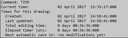
TIME
With the help of this command, you may learn a lot of details about your design, like the date it was made and the total amount of time spent altering it.
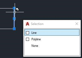
QSELECT
You may use this command to filter a selection from your drawing. For instance, you may use fast select to create a selection set that includes all of the drawing's circles with the specified radius.
DI
It may be used to determine the separation between two drawing locations.
COPYBASE
You may use a base point to clone any object with the help of this command.
PASTECLIP
Using this command, you may paste the copied objects from your clipboard into your drawing.
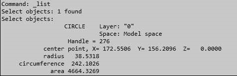
LIST
With the help of this command, you may discover a variety of information about an item, including the layer it is on, its area, length or radius, perimeter or circumference, and much more. Simply type LIST on the command line, hit Enter, choose the object from the drawing area that you want to know more about, and hit Enter once more to use this command.
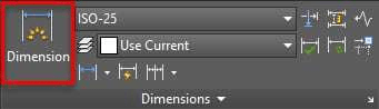
DIM
The majority of dimensions, including linear, aligned, radius, diameter, and baseline, may be created with this command, which was added to AutoCAD in version 2016 of the software. You may use the DIM command or use the DIM tool from the dimensions panel of the Annotate tab to obtain this command.
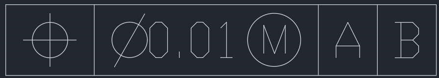
TOLERANCE
Use this command to add a feature control frame to your design that represents information about tolerances.
SCALETEXT
You can adjust the scale of an existing Text or Mtext object in the drawing with this command. For this command to work, put SCALETEXT on the command line, hit Enter, choose the text from the drawing area, and hit Enter once again.
From the command line, choose "Existing" and then "scaling factor." Type the scale to which you wish to convert the text height, then press Enter. The base point will not change even if the scale of these text entities changes.
BASE
You can alter a drawing's base point with this command without altering the drawing's origin. This is especially useful if you wish to use the graphic as an Xref in another document. The base point used by AutoCAD by default is the origin, which can be changed using this command without changing the origin.
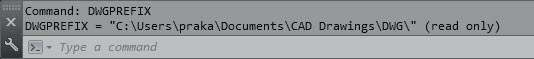
DWGPREFIX
If you have a design open in AutoCAD and are unsure of its save location, you may quickly check it up by using the DWGPREFIX command. This command may be used to locate associated Xrefs in the drawing rapidly.
TJUST
You may use this command to modify the text justification of the drawing's Text and Mtext components.
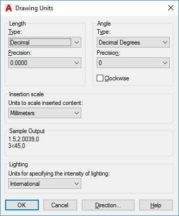
UNITS
The accuracy of the linear and angular dimensions, as well as the default rotation angle, may all be adjusted with this command.
ML
You may create a multiline geometry that has several parallel lines by using this command.
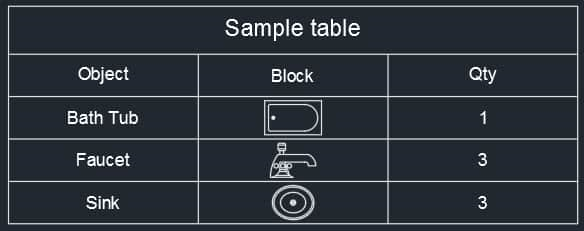
TINSERT
Using this command, you may add a block or a graphic as a block to the table. With the TINSERT dialogue box, you can also fit the block into the table cell and automatically justify its placement. By importing blocks from Design Center, as seen in the figure below, I created a straightforward table.
MIRRTEXT
By default, AutoCAD does not mirror text in the design. If you wish to change this, set the MIRRTEXT system variable's value to 1.

AREA
This command may be used, as its name implies, to locate the region of closed or open forms in an AutoCAD drawing. Refer to this linked page for further information on locating the region in AutoCAD designs.
Related: Here are three alternative methods for finding area in AutoCAD designs.
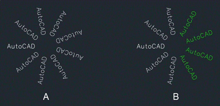
TORIENT
You can reorient text entities with this command to make them easier to read. The text in picture A below is positioned at various angles, making it difficult to read in some circumstances.
ID
To determine a point's coordinate values in an AutoCAD drawing, use this command.
MINSERT
You can insert pre-existing drawing blocks as a rectangle array component by using this command. An array that has been inserted with the MINSERT command cannot be exploded.
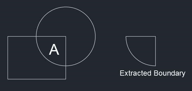
BOUNDARY
You may extract closed borders from any enclosed region with this command. Numerous more uses, such as calculating the contained region's area, are possible using this border. The Border command was used to extract the boundary of the region designated as A as a polyline in the image below.
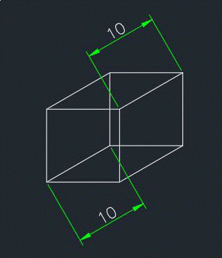
DIMROTATED
This command can be used to tilt a dimension line toward the positive side of the X-axis at a specific angle. The dimensions in the example below were created using the DIMROTATED command.
BREAKLINE
This tool may be used to draw a Breakline sign on a line. Enter the command BREAKLINE, then select the scale option from the command line to apply the proper scale to the breakline.
Choose the breakline's beginning and ending points, then click anywhere along the line to set its position. You may also just hit enter to insert the breakline right in the middle of the line.

TXT2MTXT
This command allows you to merge numerous Mtext objects into a single Mtext unit as well as transform a text object into a Mtext object.
SAVEALL
This command may be used to save all open drawings in the AutoCAD window, as the name implies.