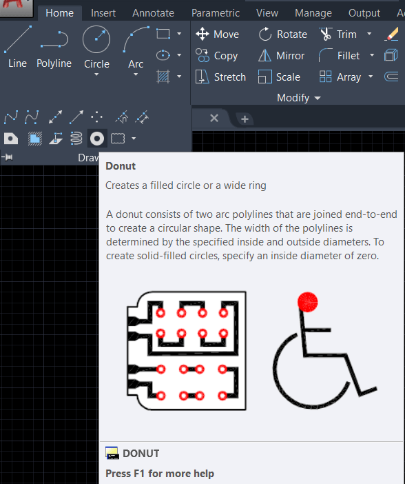
Donut Command in AutoCAD
A donut is formed by joining two arc polylines end to end to form a circular shape. The selected interior and outer diameters define the width of the polylines. When the interior diameter is set to 0, the donut becomes a filled circle.
The following prompts will appear.
- Inside Dimensions
The interior diameter of the donut is specified as displayed.
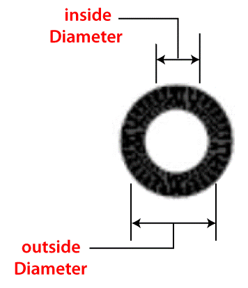
- Outside Dimensions
The donut's exterior diameter is specified.
- Donut's center
The donut's placement is determined by its center point. Until you click Enter to stop the command, a doughnut is drawn at each position you specify.
In AutoCAD, the Donut Command
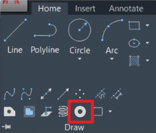
There are several choices connected to the line accessible in the Draw panel. Selecting the draw option from the drop-down menu reveals this. The draw panel drop-down menu includes choices such as Spline fit, Spline CV, Multiple points, Construction line, Ray, Multiline, Divide, Measure, Region, Helix, Donut, Revision clouds, and more.
AutoCAD's donut command
- To draw a solid-filled circle or a large circle, use this command. The Donut command creates a circular form by joining two arc polylines end-to-end.
- Select a donut tool from the draw panel drop-down menu on the home tab to activate the Donut command. Alternatively, hit Enter after typing 'DO' in the command bar.
- The selected interior and outer diameters define the width of polylines. Provide inside diameter after selecting this command.
- Set the inside direction to zero to make a Solid Circle.
- Enter the outer diameter after entering the interior diameter. A doughnut will be formed. Without leaving command, we can produce several duplicates of this doughnut.
- Press the ESC or Enter key, or right-click the mouse to exit this command.
- Because it is made up of two arc polylines, we may change the form by changing the polyline arc.
The difference between the donut and circle instructions
The difference between circle and donut as nouns is that a circle is a two-dimensional geometric object, a line, made up of all points on a plane that are equally far apart, but a donut is a doughnut.
With AutoCAD, create a doughnut
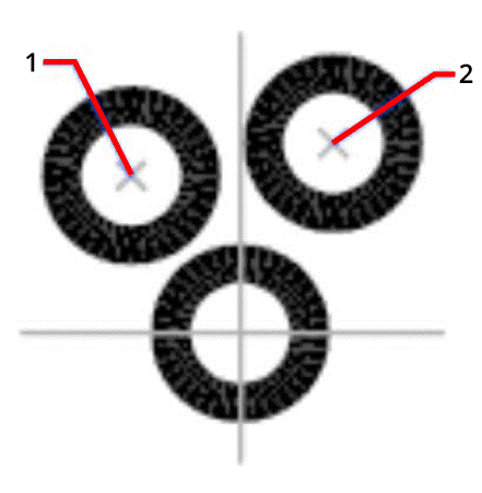
- Select Draw panel Donut from the Home menu. Find.
- Indicate the interior diameter (1).
- Determine the outside diameter (2).
- Determine the donut's center (3).
- Type another donut's center point or press Enter to finish the command.
To position a doughnut on a drawing, you'll need two values.
- Diameter of the donut (enter a value, or pick two points)
- The first item to remember regarding diameter is that (enter coordinates, or pick a point)
- The second point on the diameter – (insert coordinates or choose another location)
AutoCAD's Revcloud
- Select the Home tab. Revision Cloud drop-down draw panel Find.
- Choose Object by right-clicking in the drawing area.
- Choose a circle, ellipse, polyline, or spline to make a revision cloud out of.
- Press Enter to retain the arcs in their present path.
- Enter the code.
The default UCS in 3D AutoCAD
The Universal Coordinate System (UCS) is a Cartesian coordinate system with adjustable horizontal and vertical directions, rotation axes, and other fundamental geometric references.
AutoCAD's palette
The Tool Palette in AutoCAD allows you to access several tools. The tools from the tool menu are all over our drawing. Architectural, Civil, Manufacturing, Engineering, and other tools are included in the Tool Palette. Basic patterns, blocks, and other regularly used instructions are also included (Leader, etc.).
You can use these keys to repeat your last AutoCAD command.
Keyboard shortcuts in AutoCAD 5. ModelingCP CTRL + J Copy Rep the previous command. XExpand an item, a volume, a polyline, or anything else. 19 other lines XLStraight line
With AutoCAD, create a Pline
- Select the Home tab and then Draw panel Boundary. Find.
- In the Boundary Creation dialogue box, select Polyline from the Object Type list.
- Pick Points is the third option. Create a border polyline for each region by specifying points within it.
- Type Enter to finish the operation and generate the border polylines.
With Autodesk, navigate about
Press F3 or click Zoom. Click and drag the view to the appropriate scale using the arrow pointer. Dragging down raises the view scale, whereas dragging up reduces it. When the image has reached the necessary magnification, release the mouse button.
In AutoCAD, engrave a square in a circle
- Then choose the Drafting tab, the Draw panel, the Rectangle drop-down menu, and Polygon.
- Type the number of sides at the Command prompt.
- Determine the polygon's center.
- To make a polygon, type I and surround it with a circle of selected points.
- Enter the radius measurement.
With AutoCAD, alter the default plot style
Select Options from the Tools menu. In the Plot and Publish tab of the Options dialogue box, click the Plot Style Table Settings button. In the Plot Style Table Settings dialogue box, choose either Use Color-dependent Plot Styles or Use Named Plot Styles. (Optional) In the Default Style Table box, choose a default plot style table.