Dimension command in AutoCAD
To dimension an item, you can choose one or more of its points, and then click to set the dimension line. When you hover over an item, the DIM command automatically generates a preview of an appropriate dimension type to use.
The list of supported dimension types includes the following:
- Aligned, vertical, horizontal, and rectangular dimensions
- Standard dimensions
- Angle measurements
- Dimensions of the radius and jogged radius
- Diameter specifications
- Arc length measurements
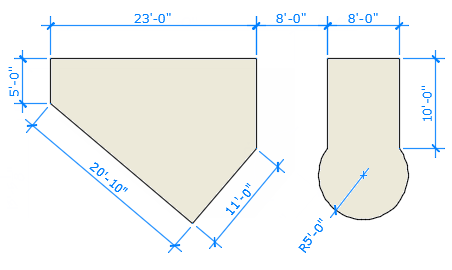
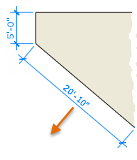
Here is an illustration of several proportions utilising the architectural dimension style and the imperial unit.
Dimensions in Lines
The DIM command allows you to construct radial, aligned, horizontal, and vertical dimensions. The type of dimension depends on the object that you select and the direction that you drag the dimension line.
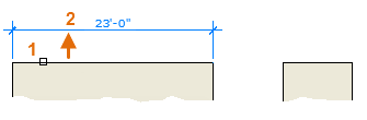
The following illustration demonstrates one method for using the DIM command. Once you start the command, select the line (1), and then click the location of the dimension line (2).
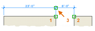
For the 8'-0" dimension below, you use another method. You start the DIM command, click two endpoints (1 and 2) and then the location of the dimension line (3).
To line up the dimension lines point 3 was snapped to the endpoint of the previously created dimension line.
Tip: If points 1 and 2 are not on the same horizontal line, press Shift to force the dimension line to be horizontal.
In addition, if the building or part being dimensioned is at an angle, enter DIMROTATED for that case.
Use the DIM command to create dimensions that are parallel to an object by dragging the dimension line at an angle rather than horizontally or vertically.
Tip: Because it is easy to accidentally snap to the wrong feature or to part of a dimension object, be sure to zoom in closely enough to avoid confusion.
Modify Dimensions
Nothing is quicker than employing grips for small dimensional modifications.
In this illustration, you choose the dimension to show its grips. Next, drag the dimension line by clicking one of the grips at its end or the grip on the dimension text and moving it to a new spot.
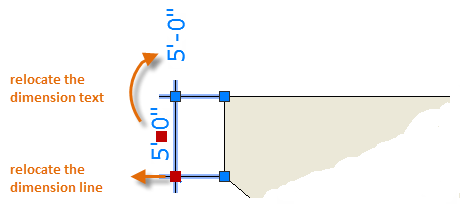
Tip: If the changes are more complicated than this, it might be faster simply to delete and then recreate the dimension.
Dimension Styles
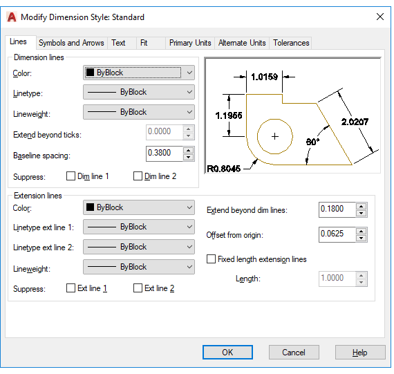
Drafting standards are created and upheld with the use of dimension styles. The DIMSTYLE command allows practically every aspect of the appearance and behaviour of dimensions to be controlled by a variety of dimension variables. Every dimension style stores these settings.
Standard (imperial) or ISO-25 is the names of the default dimension styles (metric). Up until another style is set as the current dimension style, it is allocated to all dimensions.
The drop-down list of the Annotation panel shows the name of the current dimension style, in this case Hitchhiker.
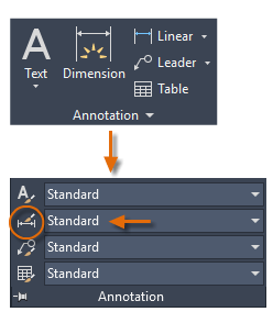
Click the corresponding button to launch the Dimension Style Manager. Although it will take effort to fully specify them, you can design dimension styles that adhere to almost any standard.
Radial Dimensions
An optional centreline or centre mark is used to measure the radius or diameter of arcs and circles using radial dimensions. The picture shows a number of alternatives.
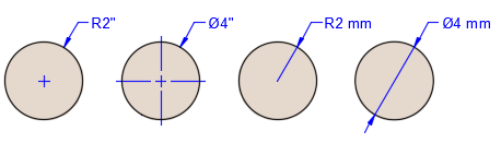
Note: When part of the dimension is located within the dimensioned arc or circle, the non-associative centreline or center mark is automatically suppressed.
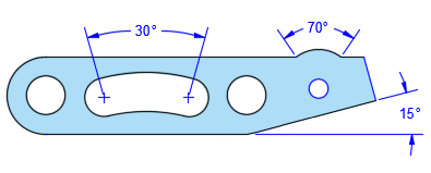
Angular Dimensions
Creates an angular dimension showing the angle between three points by or the angle between two lines (same as the DIMANGULAR command).
- Vertex. Specifies the point to use as the vertex of an angular dimension.
- Specify first side of angle. Specifies one of the lines that defines the angle.
- Specify second side of angle. Specifies the other line that defines the angle.
- Angular dimension location. Specifies the quadrant and location for the arc dimension line.
- Mtext. Edits the dimension text with the Text Editor contextual tab.
- Text. Edits the dimension text in the Command window.
- Text angle. Specifies the angle of the dimension text.
- Undo. Returns to the previous prompt.
Angular dimensions measure the angle between two selected geometric objects or three points.
From left to right, the example shows angular dimensions created using a vertex and two points, an arc, and two lines.
Ordinate Dimensions
Ordinate dimensions measure the perpendicular distances from an origin point called the datum, such as a hole in a part. These dimensions prevent escalating errors by maintaining accurate offsets of the features from the datum.
Creates an ordinate dimension (same as DIMORDINATE command).
Feature location. Prompts for a point on a feature such as an endpoint, intersection, or center of an object.
Leader endpoint. Uses the difference between the feature location and the leader endpoint to determine whether it is an X or a Y ordinate dimension. If the difference in the Y ordinate is greater, the dimension measures the X ordinate. Otherwise, it measures the Y ordinate.
Xdatum. Measures the X ordinate and determines the orientation of the leader line and dimension text.
Ydatum. Measures the Y ordinate and determines the orientation of the leader line and dimension text.
Mtext. Displays the Text Editor contextual tab, which you can use to edit the dimension text.
Text. Customizes the dimension text at the Command prompt. The generated dimension is displayed within angle brackets.
Angle. Specifies the angle of the dimension text.
Undo. Returns to the previous prompt.
Undo. Returns to the previous prompt.
Important: The datum is established by the current location of the UCS origin.
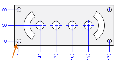
In this example, the datum (0,0) is indicated as the hole in the lower-left corner of the illustrated panel.
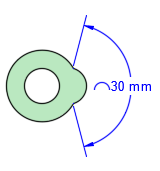
Arc Length Dimensions
Arc length dimensions measure the distance along an arc or polyline arc segment. Typical uses of arc length dimensions include measuring the travel distance around a cam or indicating the length of a cable.
To differentiate them from linear or angular dimensions, arc length dimensions display an arc symbol by default. The arc symbol, also called a hat or cap, is displayed either above the dimension text or preceding the dimension text.
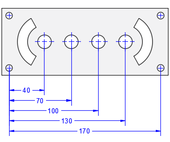
Baseline and Continued Dimensions
Creates a linear, angular, or ordinate dimension from the first extension line of the previous or selected dimension (same as the DIMBASELINE command).
Note: By default, the last created dimension is used as the base dimension.
First extension line origin.
Specifies the first extension line of the base dimension as the extension line origin for the baseline dimension.
Second extension line origin. Specifies the next edge or angle to dimension.
Feature Location. Uses the endpoint of the base dimension (ordinate dimension) as the endpoint for the baseline dimension.
Select. Prompts you select a linear, ordinate, or angular dimension to use as the base for the baseline dimension.
Offset. Specifies the offset distance from which the baseline dimensions are created.
Undo. Undoes the last baseline dimension created.
Continued dimensions, also called chained dimensions, are multiple dimensions placed end-to-end.
Creates a linear, angular, or ordinate dimension from the second extension line of a selected dimension (same as the DIMCONTINUE command).
- First extension line origin. Specifies the first extension line of the base dimension as the extension line origin for the continued dimension.
- Second extension line origin. Specifies the next edge or angle to dimension.
- Feature location. Uses the endpoint of the base dimension (ordinate dimension) as the endpoint for the continued dimension.
- Select. Prompts you select a linear, ordinate, or angular dimension to use as the base for the continued dimension.
- Undo. Undoes the last baseline dimension created.
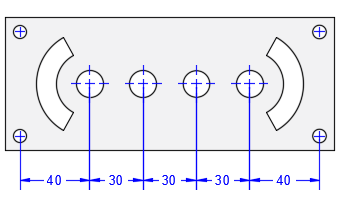
Baseline dimensions are multiple dimensions with offset dimension lines measured from the same location.
Note: Before you can create continued or baseline dimensions, you must first create a linear, angular, or ordinate dimension to act as a base dimension from which to reference the subsequent dimensions.
Current Layer Override
By default, all new objects are created on the current layer. For new dimension objects, you can specify a default layer that's different than the current layer by specifying the layer with the DIMLAYER system variable.
Rotated Views
Leader landings, components of dimensions, and text objects determine their horizontal and vertical directions from the UCS axes at the time when they are created.
If a view in a drawing is rotated, you can first use the UCS /View option to set the horizontal and vertical directions relative to the drawing rather than the rotated view. Some DIM options set a mode of operation that persists until you change it, including
- Baseline linear or baseline angular dimensioning
- Continue linear or continue angular dimensioning
- Radius, diameter, jogged radius, or arc length dimensions
- Some DIM options provide methods to edit dimensions including
- Align the dimension lines of selected dimensions to a reference or base dimension
- Offset the dimension lines of selected dimensions
- Specify a different layer for subsequently created dimensions
Align
Aligns multiple parallel, concentric, or same datum dimensions to a selected base dimension.
Base dimension. Specifies a dimension to use as basis for the dimensions alignment.
Dimensions to align. Selects the dimensions to align to the selected base dimension.
Distribute
Specifies the method on how to distribute a group of selected isolated linear or ordinate dimensions.
- Equal. Equally distributes all selected dimensions. This method requires a minimum of three dimension lines.
- Offset. Distributes all selected dimensions at a specified offset distance.
Layer
Assigns new dimensions to the specified layer, overriding the current layer. Enter Use Current or ". " to use the current layer. (DIMLAYER system variable)
Undo
Reverses the last dimension operation.
The following options are displayed when you place a dimension in such a way that it overlaps an existing dimension.
Move away
Arranges the existing dimension and the newly inserted dimension into a baseline dimension type.
Break up
Splits up the existing dimension into two dimensions, and arranges those dimensions into a continued dimension type.
Replace
Deletes the existing dimension and replaces it with the one you insert.
None
Inserts the new dimension on top of the existing dimension.
The following prompts are displayed.
Select objects
Defaults to an applicable dimension type for the objects you select and displays the prompts corresponding to that dimension type.
| Object type | Default |
| Arc | Radius dimensions |
| Circle | Diameter dimensions |
| Line | Linear dimensions |
| Polyline | Linear or radius dimensions, depending on the segment selected |
Align
Aligns multiple parallel, concentric, or same datum dimensions to a selected base dimension.
- Base dimension. Specifies a dimension to use as basis for the dimensions alignment.
- Dimensions to align. Selects the dimensions to align to the selected base dimension.
Distribute
Specifies the method on how to distribute a group of selected isolated linear or ordinate dimensions.
- Equal. Equally distributes all selected dimensions. This method requires a minimum of three dimension lines.
- Offset. Distributes all selected dimensions at a specified offset distance.
Layer
Assigns new dimensions to the specified layer, overriding the current layer. Enter Use Current or " . " to use the current layer. (DIMLAYER system variable)
Undo
Reverses the last dimension operation.
The following options are displayed when you place a dimension in such a way that it overlaps an existing dimension.
Move away
Arranges the existing dimension and the newly inserted dimension into a baseline dimension type.
Break up
Splits up the existing dimension into two dimensions, and arranges those dimensions into a continued dimension type.
Replace
Deletes the existing dimension and replaces it with the one you insert.
None
Inserts the new dimension on top of the existing dimension.