Magnetic Core Memory
Magnetic-core memory is the most common type of random-access memory in computers for almost 20 years, between 1955 and 1975. Such memory is sometimes referred to as core memory, or, colloquially, core.
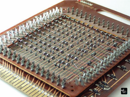
Core memory employs toroids (rings) made of a soft magnetic material (often semi-hard ferrite). Each core contains a single bit of information. Each core is connected by two or more wires, resulting in an X-Y array. When a voltage greater than a particular threshold is delivered to the cables, the core becomes magnetic. The part of the core that is written is determined by charging one X along with a Y wire to 50% the needed power, resulting in only the one core at the point of intersection being written. Depending on which way of the electrical currents, the heart will detect a clockwise or clockwise magnetic field and store a 1 or 0.
The writing operation also induces electricity into neighbouring cables. If the new pulse supplied to the X-Y wires is identical to the previous pulse supplied to the core, the existing fields will have no effect, and no induction will occur. If the new heartbeat goes in the other direction, an impulse will be formed. This is generally detected on an additional "sense" cable, allowing the computer to determine whether the core carried a 1 or 0. Because this readout technique needs the core to have been written, it is referred to as a harmful readout, and it necessitates extra circuitry to restore the core back to its initial value if the procedure flips it.
When not being viewed or written, the semiconductors retain their last value, even if the electricity is switched off. Thus, they are classified as non-volatile memory. Based on how it was connected, core memory might be quite dependable. Read-only core rope recall, for example, was employed in the Apollo Guidance Computer, which was key to NASA's flawless Moon landing.
Using smaller cores and wires, memory density of the core gradually increased. By the late 1960s, a density of around 32 kilobits per cubic meter (0.9 kilobits per litre) became common. During this time, the cost fell from roughly $1 per piece to around 1 cent per bit. Reaching this density necessitated highly precise manufacturing, which was nearly exclusively done by hand despite repeated major attempts to computerize the process. Core was nearly universal until the arrival of electronic memories in the late 1960s, particularly dynamic RAM (DRAM) in the beginning of the 1970s. Initially priced similarly to core, DRAM is smaller and easier to utilize. Since 1973, core was steadily forced out of the market.
Although the term "core memory" is no longer used, memory in machines is still referred to as "core" despite the fact it is constructed of semiconductors, especially by those who have worked on computers with true core memory. The files created by storing the full contents of memory on a hard drive for assessment, which is now often done automatically when a serious error happens within an electronic program, are still referred to as "core dumps".
How does Core Memory Work?
The most common type of core recall, X/Y line coincident-current, is used for a computer's main memory. It comprises plenty of small toroidal magnetic ceramic iron oxides (cores) held within a grid-like arrangement (i.e. as a "stack" of sections called planes), in wires woven through the openings in the cores' centers. Early systems used the four wires: X, Y, Sense, which is and Inhibit; however, subsequent cores consolidated the last two wires into a single Sense/Inhibit line. Each toroid held a single byte (0 or 1). One bit on every plane was able to access in a single cycle; hence every computer word in a word array was distributed across a "stack" of aircraft.
Each plane would modify one portion of an expression in parallel, enabling the entire word to get read or typed in a single cycle.
Core is based on the square loop of hysteresis features of the ferrite rock used to manufacture the toroids. A magnetic field is created when an electric current flow through a wire that contains a core. Only a magnetic field with strength greater than a specific threshold ("select") can induce the core to shift its magnetic polarity. To pick a place in the memory, one of the two X and Y lines is driven using half the amount of power ("half-select") needed to effect the change. Only the sum of the magnetic field created wherever the X and Y lines intersect (a logic AND functional) is sufficient to alter the state; the remaining cores are going to observe only half the required field ("half-selected"), if any at all. By sending electricity through the wires in a certain direction, the induced field causes the magnetic flux of the chosen core to cycle in one of two directions (clockwise or counterclockwise). One way indicates a stored 1, whilst the opposite is a stored 0.
A toroidal core is favoured since the magnetic route is closed, there aren't any poles that are magnetic, and there is thus not much external flux. This permits the insides to be packed tightly without the magnetic field interfering. The diagonal sensing wires made it necessary to employ alternate 45-degree placement in early core arrays. With the removal of these lateral wires, tighter packaging became feasible.
Other types of Core Memory
Word line memory in the core was commonly utilized to supply register memory. The additional terms for this kind are linearly select and 2-D. This type of core memory normally connected three wires with every core on the plane: phrase read, phrase write, and bits sense/write. To read of clear words, the entire current is supplied to a number of word reading lines, clearing the selected core and any that flip produce voltage surges within the bit sense/write lines. Normally, a single word read line is selected for read; however, for clear, several words read lines can be chosen while the bits of sense/write lines are disregarded. To write words, apply half current to one or more words write lines, and then set a bit by applying half current to every bit sense/write line. In other systems, the word reading and word write wires were integrated into just one wire, creating a memory array using only two wires per bit. Multiple word writing lines can be specified. This provided a performance benefit over X/Y lines coincident-current because many words could be deleted or written using the same value in just one cycle. A normal machine's register set typically included only one tiny plane of this type of core memory. This method was used to build some extremely large memories, like the one used for Expanded Core Storage (ECS) extra memory of the CDC 6600 that could store up to 2 hundred million 60-bit words.
Reading and Writing in Magnetic Core Memory
Reading
- To read a bit from core memory, the electronics attempts to flip the information to the orientation corresponding to the 0 state by driving the specified Y and X lines that cross at the core.
- If the bit was previously set to 0, the physical condition of the core remains unaltered.
- If the bit had been set to 1, the core will shift magnetic polarity. This change, with a delay, generates an electrical pulse in the Sense line.
- The detection that this is a pulse indicates that the bit most recently held a one. Absence of any pulse indicates that the bit held a 0. The delay in perceiving the pulse of voltage is referred to as the core memory's access time.
Writing
- To write an instruction of core memories, the wiring assumes that the bit has been read and is in the 0 condition.
- To write a single bit, the chosen X and Y wires are driven with power in the same direction as the read operation. Similarly to the read, the core of the magnet at the junction of both the X and Y lines reverses magnetic polarity.
- There are two techniques for writing a zero bit. The first is identical as the reading procedure with the current flowing in the initial direction. The second follows a logic that is flipped. To put it another way, writing a 0 bit prevents the creation of a 1. The identical amount of electricity is sent via the Inhibit line. This decreases the net current passing through the core to half of the select current, preventing polarity changes.
Physical Characteristics
Speed
In today's standards, early core memory performance is about similar to an operating rate of 1 MHz In the early 1970s, core memory structures had cycle durations of 6 µs, but by the mid-70s, they had decreased to 1.2 µs and 600 ns (0.6 µs).In 1964, theComputer Corporation (CDC) 6600 featured a memory cycle duration of 1.0 µs and used cores with a half-select power of 200 mA, indicating significantly faster performance. Everything feasible was done to reduce access times and enhance data rates (bandwidth), included the use of several core grids, each of which stored one bit of a data word. For example, a machine may have 32 grids of cores, each having a single bit from a 32-bit word, and the control unit could access the complete 32-bit term in a single read and write operation.
Reliability
Core memory has non-volatile storage, meaning it can maintain its data indefinitely without power. It is additionally relatively resistant to EMP and radiation. These were significant advantages for some applications, such as the first-generation commercial programmable controllers, military facilities and vehicles such as fighter aircraft and spacecraft, and resulted in core being used for several years after semiconductor MOS memory became available. For instance, the Space Shuttle's IBM AP-101B flying computer featured core memory, which kept the contents in memory even after the Challenger disintegrated and crashed into the sea in 1986.
Temperature Sensitivity
Another feature of early cores was that the force of coercion was extremely temperature-sensitive; the correct half-select current at a particular temperature was not the same as at another. As a result, the memory controller would contain a temperature sensor (usually a thermistor) to accurately alter the current levels in response to temperature variations. One example is the core memory utilized by Digital Equipment Corporation, or DEC, for its PDP-1 computer; this concept was carried over into all of DEC's subsequent core memory systems created for their PDP series of air-cooled computers.
Another way for dealing with sensitivity to temperature was to surround the magnetic center "stack" in a temperature-controlled oven. Examples include the IBM 1620's heated-air core memory, which might take up to 30 minutes to achieve operational temperature of roughly 106 °F (41 °C), as well as the IBM 7090, earlier IBM 7094s, and IBM 7030's heated-oil-bath core memory. The core was heated rather than cooled since the key requirement was a steady temperature, which was easier (and less expensive) to maintain an elevated temperature substantially above the ambient temperature than either at or below it.
Diagnosing
To diagnose hardware faults in core memory, time-consuming diagnostic tools have to be run. While a fast test determined whether or not each bit might have a one and a zero, other diagnostics examined the heart of memory with worst-case scenarios and required many hours to complete. Because most computers had only one core-memory the same page, these diagnostics travelled about in memory, allowing you to test every bit. The "Shmoo test" was an advanced test whereby the half-select winds were changed as well as the moment at which the sensing line was checked ("strobed"). The data plot for this test appeared similar to a cartoon character named "Shmoo," so the name stuck. In many cases, mistakes may be corrected by lightly tapping the circuit board that is printed on the core arrays on a table. This somewhat altered the placements of the core along the wires that ran through them, which might resolve the issue. The approach was rarely used since core memory outperformed other parts of the machine of the time.
Uses of Magnetic Core Memory
- The non-volatile nature of this device makes it ideal for supplementary storage.
- Magnet core memory is employed as computer memory due to its behaviour when a magnetic field from outside is introduced.
- It can function as a storage device.
- Magnetic core memory captures the minds of current enthusiasts.
Advantages
- Lower cost compared to high-performance gas tube and transistor memory.
- Improved performance over low-cost drum memory.
- It is quite volatile in nature.
- The parts had a longer life expectancy, and their operational properties did not change over time.
- The magnetic core requires no electricity to maintain its data.
Disadvantages
- Magnetic core memory is being replaced with semiconductor memory since each embedded circuit in silicon memory comprises hundreds of semiconductor devices totalling millions of bits.
- Magnetic core memory does not become smaller than the amount required by a basic calculator.
- Reading a single bit from a core resets its state to zero, which is referred to as destructive reading, and restoring the prior bit requires a write cycle.