The Data Link Layer Frame Fields
Introduction
Sending data as a stream of bits between two computers or other devices over a point-to-point cable connection is known as Framing. These fragments must, nevertheless, be organized into coherent informational blocks. One feature of the data link layer is Framing.
During data transmission, bits must move from the source to the destination synchronously in the physical layer. This section will focus on point-to-point data transmission between two devices. After receiving packets from the network layer, the data link layer adds the source and destination addresses to each packet. They are converted into frames at the data connection layer. A packet is split up into smaller frames as the frame size increases. More effective flow control and error control are made possible by these smaller frames.
Data Link Layer Framing
A point-to-point connection known as Framing is made up of a wire through which a stream of bits carrying data is sent between two devices.
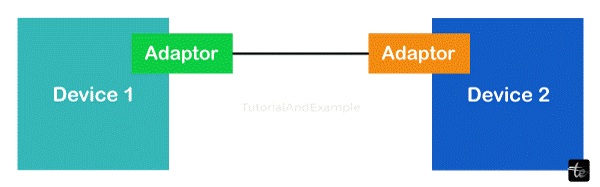
Let's understand this using the provided diagram.
Each of the two devices we've provided has an adaptor attached to it. The data will be transformed into signals by this adaptor, which will then pass through the cable and be absorbed by the physical layers of other devices.
Data is sent and received over a computer network using frames thanks to Framing. The data link layer packs bits into frames so that each frame may be identified from the others.
To be ready for transmission across local media, the data link layer encapsulates a packet in a frame that has a header and a trailer.
A frame is a unit of data that travels between different network nodes in telecommunications.
The header field and trailer field, which frame the data and move it bit by bit serially, usually make up a frame. These frames can only be understood by the data link layer.
Working of Framing
The process of Framing involves dividing data into manageable, smaller units called frames. A payload, or the actual data, and a header, or control information, make up each frame. After adding the header, the sender transmits the frame across the network. In order to ensure correct delivery, the receiver then extracts the header, processes the data, and looks for errors. Data transmission between devices is made reliable and efficient by this process.
Because Framing makes error detection and recovery possible, it is necessary for effective data transfer. Because the data is divided into smaller frames, only that particular frame—rather than the entire data packet—needs to be retransmitted in the event that any frame is lost or corrupted during transmission. The header data also aids in error correction and guarantees that the data is sent correctly to the intended recipient. This process ensures reliable interaction among devices in a network.
Problems in Framing
Detecting the start of the frame: A frame has to be detectable by all stations at the time it is transmitted. The way the station finds frames is by searching for the SFD (Starting Frame Delimiter), a unique set of bits that indicates the start of a frame.
How does the station detect a frame: Via a sequential circuit, each station listens to link for SFD pattern. The sequential circuit alerts the station if SFD is found. To accept or reject a frame, the station verifies the destination address.
Detecting end of frame: When to wrap up your frame reading.
Handling errors: Noise and other transmission errors can lead to framing errors, which can lead to a station misinterpreting the frame. As a result, error detection and correction methods, such as the cyclic redundancy check (CRC), are used to ensure the integrity of the frame.
Framing overhead: Each frame consists of a header and a trailer containing control data, error detection code, source, and destination addresses, and other protocol-specific data. The bandwidth that is available for data transmission is decreased by this overhead, particularly for small-sized frames.
Framing Incompatibility: Framing incompatibility problems may arise because different networking devices and protocols employ different framing techniques. For example, suppose a device utilizing one framing method sends data to a device using a different framing method. In that case, the receiving device might not be able to interpret the frame correctly.
Framing synchronization: Stations need to be in sync with one another in order to prevent collisions and guarantee dependable communication. In order to achieve synchronization, all stations must concur on the timing and frame boundaries, which can be difficult in intricate networks with lots of devices and fluctuating traffic loads.
Framing efficiency: The goal of framing design should be to maximize available bandwidth for data transmission while minimizing data overhead. Higher latency and poorer network performance can result from ineffective framing techniques.
Different Computer Network Framing Types
Framing is separated into two categories:
Fixture-size Framing
Because the frame size in this style of Framing is fixed, the frame length serves as the frame's delimiter.
After receiving the first 50 bits of data, the receiver will immediately recognize that the following 50 bits are of frame two, and so on if a device is sending 200 bits of data and the frame size is fixed at 50 bits. By using this Framing, extra boundary bits are not required to indicate the beginning and finish of the frame.
Drawback: Internal fragmentation happens when the data size is less than the frame size. Padding is a simple solution to stop this kind of problem.
An easy way to prevent this kind of thing is with padding.
Variable size Framing
A technique for breaking up data into frames where each frame can have a different size is called variable size framing. With this method, the amount of data that must be sent at any given time determines the dynamic length of each frame. For instance, of 200 bits of data, 100 bits might make up frame 1, 25 bits make up frame 2, and the remaining bits make up frame 3.
Variable size framing has the benefit of enabling more effective network bandwidth utilization. When less data needs to be transferred, smaller frames are used, which lowers overhead and boosts data transfer efficiency. However, in order to maximize data throughput, larger frames are used when sending a greater amount of data.
Many network protocols, particularly those that need adaptive data transmissions, like streaming applications or real-time communication systems, frequently use variable-size Framing. By employing this method, the network can maximize data transfer in accordance with the data load and network conditions at the moment and adapt to changing data demands.
Because each frame to be communicated in this sort of Framing may vary in size, additional mechanisms are maintained to indicate when one frame stops and the next one begins.
Length Field: This part of the frame structure indicates the length of the data or frame. The number of bytes of data that should be expected in the frame to be sent to the receiving device is specified in this field. The exact format and location of the length field within the frame may vary depending on the data link layer protocol in use.
Delimiter End: The end of a frame is indicated by a special character or sequence. It notifies the receiving device that the entire frame has been successfully received and that it is now prepared to begin processing the received data.
Byte–stuffing: By using a technique known as "character stuffing," also known as "byte stuffing," reserved patterns or unwanted control characters are removed from transmitted data frames. Inserting distinct control characters into the data is necessary to distinguish it from control characters used for signaling or Framing.
Bit–Stuffing: In order to make sure that particular control bits or patterns within a data stream don't get confused with control bits used for signaling or Framing, bit stuffing is a technique. To differentiate them from control bits, additional bits must be inserted into the data stream. Bit stuffing is primarily used to make sure that a receiver can recognize the beginning and end of data frames with accuracy and clarity. In communication protocols, this method is frequently employed to handle unique bit sequences that could be misinterpreted in other circumstances.
Benefits of Data Link Layer Framing
- Time-division multiplexing is a process that uses frames continuously.
- It makes it easier for the sender to send a set of valid bits to a recipient.
- Additionally, error-checking codes and other information are contained in the headers of frames.
- There are various data link layer techniques, such as Ethernet frame structures, frame relays, and token rings.
- Frames can be used to separate the data into several recoverable pieces, enabling further corruption examination.
- It offers a mechanism to control frame flow, preventing fast senders from causing data congestion on sluggish receivers.
- It offers reliable services for data transfer between the peer network's levels.
In the data link layer, Framing presents additional difficulties, such as:
Variable frame length: Changes in frame length might result in transmission inefficiencies depending on the data being transferred. To address this issue, protocols like HDLC and PPP use a flag sequence to identify the beginning and end of each frame.
Bit stuffing: By adding extra bits to the data stream, the method known as "bit stuffing" keeps data from being viewed as control characters. Bit stuffing, however, might result in synchronization problems and higher transmission overhead.
Synchronization: Accurate data frame transmission and reception depend on synchronization. However, maintaining synchronization can be difficult, especially in high-throughput networks where frames move quickly.
Error detection: Data Link Layer protocols employ a variety of methods, including CRCs and checksums, to identify mistakes in the data being transmitted.
Efficiency: Making effective use of the available bandwidth is necessary to ensure reliable and fast data delivery.
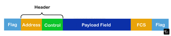
Data Link Layer Frame Fields
The components of a data link layer frame are as follows:
- Frame Header: It includes the control bytes as well as the source and destination address of the frame.
- Payload Field: It includes the delivered message.
- Trailer: Both the error correction and error detection components are present. Another term for it is a Frame Check Sequence (FCS).
- Flag: The start and finish of the frame are indicated by two flags at each end.
Frame Header
The destination address, source address, and three control fields—kind, seq, and ack—found in a frame header serve the following functions:
- Kind: This field indicates whether the frame is used for link management, error, flow control, or other control functions or whether it is a data frame.
- seq: This includes the frame's sequence number, which the recipient can use to rearrange out-of-sequence frames and send acknowledgments.
- Ack: When piggybacking is used, this contains the acknowledgment number of some frames.
Specific Data Link Layer Frames
Depending on the protocol being used, the data link layer frame may have a different structure. Let's look at the frame structure that the Point-to-Point Protocol (PPP) and High-level Data Link Control (HDLC) protocols use.
Point–to–Point Protocol
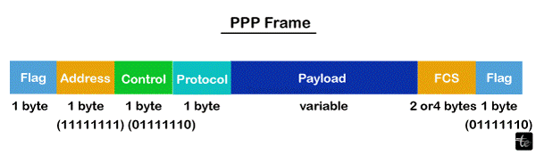
When two computers are directly connected (point-to-point), multiprotocol data is sent between them using a data connection layer communication protocol called Point-to-Point Protocol (PPP). A PPP frame's fields are:
- Flag: It has the bit pattern 01111110 and is composed of 1 byte.
- Address: 1 byte, set to 11111111 in the event that it is broadcast.
- Control: 1 byte with the value 11000000 set as a constant.
- Protocol: A byte or two indicating the kind of data that will be in the payload field.
- Payload: The network layer data is transported here. The maximum length for the payload field is 1500 bytes.
- FCS: It is a two- or four-byte frame check sequence for error detection. Cyclic redundancy code, or CRC, is the standard code used.
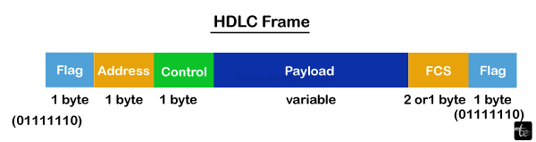
High-level Data Link Management
To transfer data among network nodes or points, a set of data link layer communication protocols known as High-level Data Link Control (HDLC) is utilized. The fields of an HDLC frame are:
- Flag: 01111110 is the bit pattern for the 8-bit sequence.
- Address: It includes the address of the recipient. One or more bytes may be present in the address field.
- Control: 1 or 2 bytes carry the flow & error control information.
- Payload: The network layer data is transported here. The length of it may vary throughout networks.
- FCS: It is a two- or four-byte frame check sequence for error detection. The standard code that is employed is called the CRC (cyclic redundancy code).
Conclusion:
The domains, challenges, benefits, and framing issues of the data link layer are now thoroughly understood.