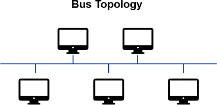
What is Bus Topology?
A bus topology is a network configuration in which all devices are connected to a single central cable, called the bus or backbone. Data is transmitted along the bus in both directions and all devices on the network can receive the data, but only the device for which the data is intended can process it. This type of topology is relatively simple and inexpensive, but can be less reliable than other types of network topologies because if the central cable fails, the entire network goes down.
In bus topology, all devices are connected to a single cable (backbone), which acts as the main communication channel for the entire network. The bus is usually a coaxial cable, but it can also be made of twisted pair or fiber optic cable. Data is transmitted along the bus in both directions and all devices on the network can receive the data. However, only the device for which the data is intended can process it. This is achieved through the use of unique addresses, or MAC addresses, assigned to each device on the network.
A bus topology is relatively simple and inexpensive to implement as it requires only one cable to connect all devices. It is also easy to expand by adding more devices to the network. However, it has some disadvantages as well. For example, if the central cable (bus) fails, the entire network goes down. Additionally, as the number of devices on the network increases, the bus can become a bottleneck and slow down the network's performance.
It's also worth noting that bus topology is not suitable for large networks and it's primarily used for small networks such as home networks or small office networks.
Types of Bus Topology
There are two main types of bus topology:
1. Linear Bus Topology
In a Linear Bus Topology, all devices are connected to a single cable in a linear fashion. The cable also known as the bus or backbone, runs in a straight line and all devices are connected to it directly or through a T-connector. The T-connector is used to connect a device to the bus while still allowing the cable to continue running in a straight line.
The bus is terminated at both ends with a terminator to prevent signal reflection. Data is transmitted along the bus in both directions and all devices on the network can receive the data. However, only the device for which the data is intended can process it. This is achieved through the use of unique addresses, or MAC addresses, assigned to each device on the network.
A linear bus topology is relatively simple and inexpensive to implement as it requires only one cable to connect all devices. It is also easy to expand by adding more devices to the network. However, it has some disadvantages as well. For example, if the central cable (bus) fails, the entire network goes down. Additionally, as the number of devices on the network increases, the bus can become a bottleneck and slow down the network's performance.
Linear bus topology is not suitable for large networks and it's primarily used for small networks such as home networks or small office networks. It's not widely used today due to its disadvantages such as a single point of failure and performance issues when the network grows.
2. Distributed bus Topology
In Distributed Bus Topology, the bus is divided into multiple segments, with each segment connecting a group of devices. Each segment has its own terminator at both ends and the segments are connected by repeaters. A repeater is a device that amplifies the signal and allows it to travel longer distances.
Each segment functions independently and if one segment fails, it will not affect the other segments. This provides a level of fault tolerance and allows the network to continue functioning even if one segment goes down.
In this type of topology, data is transmitted along the bus in both directions and all devices on the network can receive the data. However, only the device for which the data is intended can process it. This is achieved through the use of unique addresses, or MAC addresses, assigned to each device on the network.
Distributed bus topology is more complex and is typically used in larger networks, such as office networks. It allows for a more efficient use of the cable, but it also increases the complexity of the network and the potential for failure. It's not widely used today as it has been replaced by other topologies like star and ring topologies which are more efficient and fault-tolerant.