What is the HDLC Protocol?
High-level Data Link Control (HDLC) is used for the transmission of the data between points. Data is arranged into frames since it is a data connection protocol.
A frame is sent to the destination for confirmation of its arrival through the network.
By this, the transfer of high-speed transmission of a large amount of data can occur. This communication cannot be supported by the requisite control procedure.
The SDLC has been used to control and construct the HDLC procedure. This procedure can also send bit strings of the obtained length in addition to characters. A frame is a data transmission unit.
History of HDLC
The ITU standardised it as LAP (Link Access Procedure), but ANSI dubbed their similar version as ADCCP.
The exact semantics of the frame fields are not specified in the HDLC standard.
It was accepted as LAPB in the X.25 protocol stack, LAPM in the V.42 protocol stack, LAPF in the Frame Relay protocol stack, and LAPD in the ISDN protocol stack.
The IEEE 802.2 LLC protocol was inspired by HDLC, and it serves as the foundation for the framing technique used with PPP over synchronous lines, which is used by many servers to connect to a WAN, mostly with Internet.
The control channel uses the same variant for both E-carrier and SONET telephone lines. Cisco HDLC employs low-level HDLC framing techniques while also including a protocol field in the standard HDLC header.
Structure of HDLC
Data is often delivered in multiples of 8 bits, although only certain variations need this; others potentially allow data alignments on boundaries other than 8 bits.
The FCS is a CRC-CCITT or CRC-32 computed over the Address, Control, and Information fields. It allows the receiver to discover problems that may have occurred during the frame's transmission, such as missing bits, reversed bits, and superfluous bits. Nevertheless, because the algorithms used to compute the FCS are designed in such a way that the likelihood of certain types of transmission defects going undetected grows with the amount of data being checked for errors, the FCS can implicitly restrict the practical size of the frame.
If the receiver's estimate of the FCS differs from the sender's, signalling that the frame includes mistakes, the receiver can either send the sender a negative acknowledgement packet or nothing at all. After getting a negative approach or timing out while receiving the positive acknowledgement, the sender can retransmit the failed frames.
Because many early communication lines had a relatively high bit error rate, the FCS was introduced because it could be easily computed by simple, quick hardware or software. Other protocols are increasingly employing more effective forward error-correcting methods.
How does HDLC Protocol Works
Data is arranged into a unit (referred to as a frame) and delivered over a network to a destination that certifies its successful arrival in HDLC. The HDLC protocol also controls the flow or timing of data transmission.
HDLC is one of the most widely used internet protocols (IP) in Layer 2 of the Open Systems Interconnection industry communication reference architecture (OSI).
HDLC defines a technique for encapsulating or formatting data into frames for synchronous transmission to remote sites over synchronous serial wide area network (WAN) networks. HDLC is a bit-stream protocol that supports full-duplex communication and uses a 32-bit checksum to detect errors. A flag byte is followed by address and control information, data bits, and a CRC byte in an HDLC frame. To originate and terminate data link connections, a control field at the beginning of a frame is employed.
The HDLC link is made up of a primary and a secondary station where the primary station gives instructions and manage the stations.
Additional layer 2 WAN protocols for point-to-point and point-to-multipoint communication include Asynchronous Transfer Mode (ATM), frame relay, and X.25.
Because the local and distant stations are physically linked, HDLC is primarily utilised in point-to-point communication and does not require addressing to be implemented at the data link layer. In this setup, one station serves as primary and the other as secondary (unbalanced point-to-point link), or both stations serve as primary and secondary (balanced point-to-point link).
HDLC may be utilised in more complicated configurations where one major connection connects to several subsidiary links (unbalanced multipoint configuration).
When the endpoints of the WAN link are terminated with CSU/DSUs, HDLC is frequently used in leased-line connections.
Transfer Modes
HDLC has two transmission modes: normal response and asynchronous balanced.
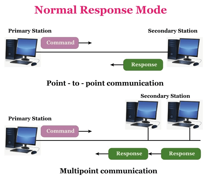
Normal Response Mode (NRM)
There are two forms of stations; the first one sends the order, and the second stations implement the instructions. It may be used for both point-to-point and multipoint communication.
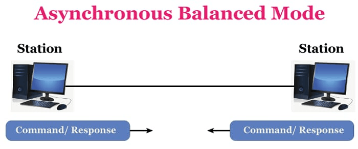
Asynchronous Balance Mode
The setup is balanced here, which means that each station may both transmit and receive orders. It is solely used for point-to-point transmission.
Asynchronous Response Mode:-
Asynchronous response mode is an HDLC enhancement. The primary/secondary distinction is maintained and the secondary station can transmit at any moment. As a result, there must be another mechanism in place to ensure that numerous secondaries do not attempt to transmit at the same time.
HDLC Frame
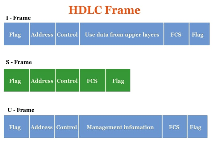
HDLC is the protocol which includes six fields per frame. The structure varies according to the kind of frame. The following are the HDLC frames:-
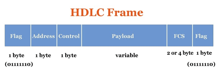
Flag: Flag shows the starting and ending point of the frame. The flag has the bit pattern 01111110. A flag sequence Field should begin and finish each frame on the connection (F). Stations linked to the data connection should continually listen for an octet flag sequence, such as 01111110. To keep the connection alive, flags are always broadcast onto the connection between frames.
Address: It has the receiver's address. This is the particular type of frame sent by primary stations, and it includes the secondary station's address(es) (s). It comprises the address of the primary station if it is transmitted by the backup station. The address field might range between one and many bytes. It may distinguish between primary and secondary station participation in frame communication or response.
Control: The control contains all the information about flow and error control.
To govern the transmission process, HDLC employs the control field (C). The field contains the instructions, answers, and sequence numbers used to support the data flow accountability of the connection.
There are three control field formats-
- The frame can send user data between two devices in an information transfer format.
- Supervisory Format: Control actions such as frame acknowledgement, re-transmission requests, and requests for momentary suspension of frames being transmitted are performed via the control field.
- Unnumbered Control Field Format: This control field format can also be utilised for control.
Payload: Payload's main work is to transfer data from thenetworkk layer. And the size of the payload changes from network to network.
FCS: A frame check sequence of two or four bytes is used to identify problems. CRC is the most often used standard code (cyclic redundancy code).
Types of HDLC Fame:-
HDLC frames are classified into three categories.
- I frame: I frame or the information framework to transfer data from user to network. They also carry information on flow and error control depending on user data. The first bit of the I-control frame's field is 0
- S frame: Information fields do not exist in S-frames or Supervisory frames. When piggybacking is not necessary, they are utilised for flow and error control. The first two bits of the S-frame control field are 10.
- U frame: U-frames, sometimes known as un-numbered frames, are employed for a range of functions, including link management. If necessary, it may include an information field.